How to use Offshore Trainer
This guide works like zooming in on a drawing. It starts with the whole site, then the platform, then the systems on it, one process path, one piece of equipment, and finally the safety material. Each level builds on the one before it.
Plan on 40 to 50 minutes the first time through. Open the trainer in a second tab and do each Try it box as you reach it.
Before you start
- Browser: use a current Chrome or Microsoft Edge on a desktop or laptop. Edge has the most natural-sounding voices, so use it if you want the spoken explanations.
- Mouse: a mouse with a scroll wheel makes moving around much easier than a trackpad.
- Nothing to install: the trainer runs in the browser. There is no login.
- Progress: lesson progress and your settings are saved in this browser on this computer. To move them, use Download my progress and Import progress on the Certificate tab under Learn (level 7).
- Going offshore soon? Read the Safety guide first. It explains alarms, mustering and escape in general terms. It never replaces the operator's orientation, the station bill, your supervisor's instructions or the water survival and helicopter training your employer requires.
- Phones and tablets: the trainer works on a phone, with the side panel behind the ☰ button. A desktop is still the better way to learn it.
What's new
November 8, 2026 (site version 4).
- Field wiring. Every gas and flame detector, shutdown valve and deluge valve now has its own rigid conduit run back to a field junction box, sealed at the device and held on strut stands, rod hangers or brackets. The floating platform has three new junction boxes with home-run conduit to the electrical building. Field runs appear in the cable schedule.
- ESD loop and control lines. Each ESD station has stainless tubing back to the wellhead control panel, and a control line runs from the panel to the actuator of every surface safety valve.
- Every load fed. The fin-fan cooler motors, the gas flotation units, the shakers, the drawworks motors and the top drive now have their feeders. The nav lights and fog signals are self-contained, with their own solar-charged batteries.
- Tray risers. Where a cable tray rises through a deck it passes through a steel curb that holds the fire-stop seal.
- Cable schedule. A new sheet lists every circuit drawn in the model: where it starts and ends, the cable, the trays it runs in and its length from terminal to terminal. Download it as CSV. The bill of materials now takes its cable lengths from the schedule.
- Cable sizes checked. The floating platform's 1,500 hp export pumps now have two cables each, and the emergency generators have enough cables in parallel to carry 115 % of their full-load current. Trays that carry both 4,160 V and 480 V cables have a divider, and each tray card states how full it is. The fuel gas heaters are fed.
- Piping completed. Every pipe end now meets a nozzle, a vessel or a tee; the skid packages have their internal piping; the flare knockout drum drains to a new sump pile on each platform.
- Safety guide. New chapters on the safety and environmental management system (stop work authority, job safety analysis, ultimate work authority), on earthing, bonding and lightning, and on PPE and confined spaces. Hot work, H2S and flaring rules added. The safety check has 13 questions.
- Geometry fixes. Compressor bottles, exhaust stacks, anodes and flanges are drawn at their true lengths and thicknesses, and mating flanges no longer overlap.
- Cables are routed with fittings. Every bend in a cable tray is now a separate 24 in radius fitting bolted in with splice plates, branches use tee fittings, and trays leave the buildings through multi-cable transits in the wall or floor. Each motor, generator and junction box that is drawn with a terminal box has its own drop: 480 V motors through rigid conduit clamped to the tray, with a seal and a flexible coupling; generators and medium-voltage motors through armored cable and glands. Instrument trays end at field junction boxes fed from below.
- Pipe supports. Every pipe line now sits on stanchions or hangs from rod hangers, spaced no farther apart than the suggested span for its size.
- Model audit. Both facilities were checked for open pipe ends, unfed motors, duplicate tags and clashes. Fixes include the flash gas compressor on the floating platform (now drawn with its electric motor), the export compressor piping, the fire wall doors at the fixed platform's electrical building, the mud return lines and the fire pump motor size.
- New facility: a deepwater tension leg platform. A floating drilling and production platform in about 3,000 ft of water, modeled from the piled foundations on the seabed to the crown of its derrick: four columns on a ring pontoon, twelve tendons, twelve dry trees on top-tensioned risers, a platform rig with a five-BOP surface stack on a dual-bore drilling riser, separation, an electrostatic treater, glycol dehydration, turbine-driven export compression, steel catenary export risers, 13.8 kV power, quarters for 150, a helideck, ten lifeboats and a rescue boat. Open it from the Facilities menu or with
/?facility=tlp. - Hull and tendon elevation. A new drawing for the floating platform: the hull, risers and tendons at one scale, with the water column between the hull and the seabed left out.
- First release: the fixed drilling and production platform. An eight-leg jacket in about 300 ft of water on the Gulf of Mexico shelf, modeled from the seabed to the crown of the derrick: piles, conductors, nine dry trees, separation, glycol dehydration, flash gas compression, oil treating and export, produced-water treatment, gas turbine power, firewater, cranes, quarters for 96, helideck, four lifeboats and boat landings.
- A platform rig on its own drilling deck. The derrick, drill floor and substructure on skid beams over the well bay, the top drive and drawworks, the BOP stack with its diverter, the closing unit, the choke manifold and mud gas separator, three mud pumps, the pits and shakers, the pipe deck and the rig's own power module, with the drilling rules from 30 CFR 250 Subparts D and G.
- Cable tray, conduit and instrument tubing are modeled. Power and instrument cables run in separate aluminum ladder trays; motor and instrument drops are in rigid aluminum conduit with seals; remote-mounted transmitters show their stands, impulse tubing and, on the gas meter, a heated enclosure.
- Drawings linked to the model: process flow diagram, electrical one-line, protection zones, four deck plans, the south elevation and the jacket elevation, each exportable as DXF.
- Coming next: isolation and permit practice, measuring tools, a jack-up drilling rig with simultaneous operations, and piping and instrument diagrams.
The whole site
Offshore Trainer is a 3D model of a complete offshore oil and gas drilling and production platform, above and below the waterline. You can orbit and zoom it, click any item to learn what it is and does, open drawings side by side with the model, follow a shutdown from the trigger to the flare, and walk the decks. Equipment is modeled to typical U.S. Gulf of Mexico practice and the federal rules that apply there. It is a training model, not a design.
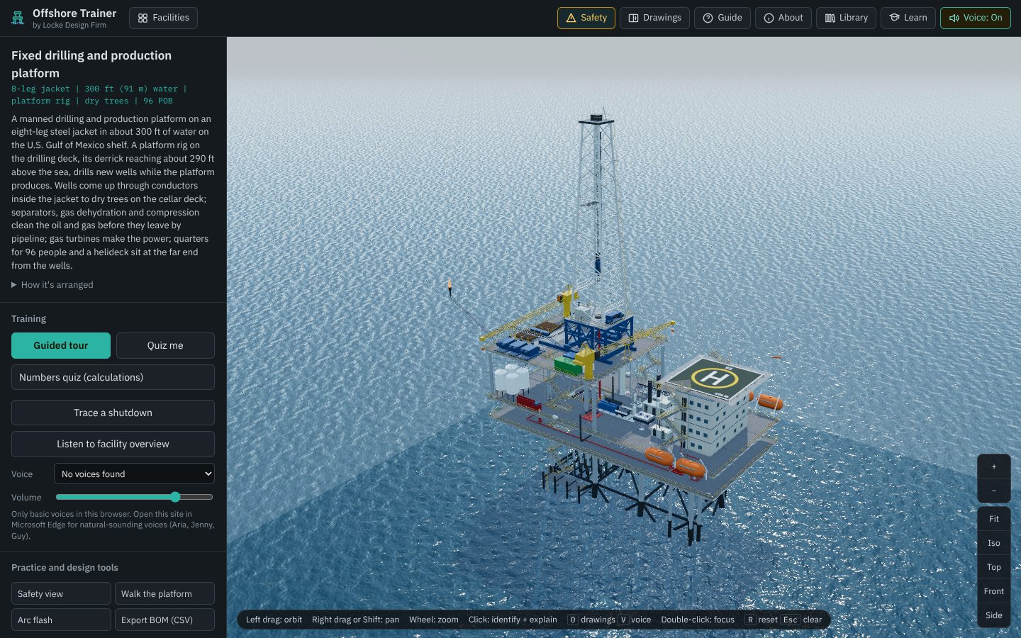
The four areas of the screen
| Area | What's in it |
|---|---|
| Header | The Facilities menu, then buttons on the right: Safety opens the offshore safety guide (level 6), Drawings opens the drawing pane (level 3), Guide opens this guide, About opens the disclaimer and references, Library opens the equipment library, Learn opens the lessons, glossary and certificate, and Voice: On / Voice: Off shows and changes whether explanations are spoken. |
| Side panel | Top to bottom: the facility name, key facts and description; Training (guided tour, quizzes, shutdown trace, voice settings); Practice and design tools; Layers and display settings; and the searchable Component catalog. On a narrow screen it hides behind the ☰ button. |
| 3D view | The model with its labels. Zoom and view buttons sit on the right edge, and a strip of mouse hints runs along the bottom. |
| Drawing pane | Opens on the right when you press Drawings or O. The 3D view shrinks to make room. |
The facilities
The site has two facilities and will grow. Each facility also has a page of its own under Facilities with its description, tour stops and equipment list.
| Facility | Key facts | What it teaches |
|---|---|---|
| Fixed drilling and production platform | 8-leg jacket, about 300 ft of water, platform rig, 9 dry-tree wells, 96 people on board | How a shelf platform is built, how a platform rig drills a new well beside producing wells, and how the process, power and safety systems fit together: wells and safety valves, drilling and well control, separation, gas dehydration and compression, oil treating and export, produced water, power, firewater, lifting, quarters and escape. |
| Deepwater tension leg platform | 4-column TLP, about 3,000 ft of water, platform rig, 12 dry-tree wells, 150 people on board | How a deepwater platform floats and is held on station by tendons, why a TLP can have dry trees on deck, how top-tensioned and catenary risers work, what changes for drilling from a floating facility (the surface BOP, the dual-bore riser), and the Coast Guard lifesaving rules for floating units. |
| Jack-up drilling rig (planned) | 350 ft independent-leg jack-up | Drilling next to a producing platform, and the extra controls when two operations share one location. |
Where to start card
The first time you open the trainer, a card offers four starting points: the guided tour if you are new to offshore, the drawings if you are a designer, the walk if you are heading offshore, and the safety guide. Close it with Esc or the ×; it will not come back on that browser.
Links to a facility or an item
A link such as /?facility=fixed&part=separator opens the trainer on that facility with every separator highlighted. The library and the equipment reference use these links, and you can send one to a trainee.
The platform
Mouse and keyboard
| Do this | To |
|---|---|
| Left drag | Orbit around the point you are looking at |
| Right drag, or Shift + drag | Pan |
| Scroll wheel | Zoom |
| Click | Identify an item and open its info panel (level 5) |
| Double-click | Fly to that item and center on it |
| R or Fit | Go back to the whole platform |
On a phone, drag with one finger to orbit, pinch to zoom and drag with two fingers to pan.
Standard views
The buttons on the right edge give Iso (three-quarter view), Top (plan), Front and Side (elevations), and + / − for zoom.
Labels change as you zoom
Turn on Labels under Layers. From far away only the large items are labeled; as you zoom in, smaller items get labels too. Each label shows the item name and its tag (V-100, PSV-100, G-1), the same tag used on the drawings.
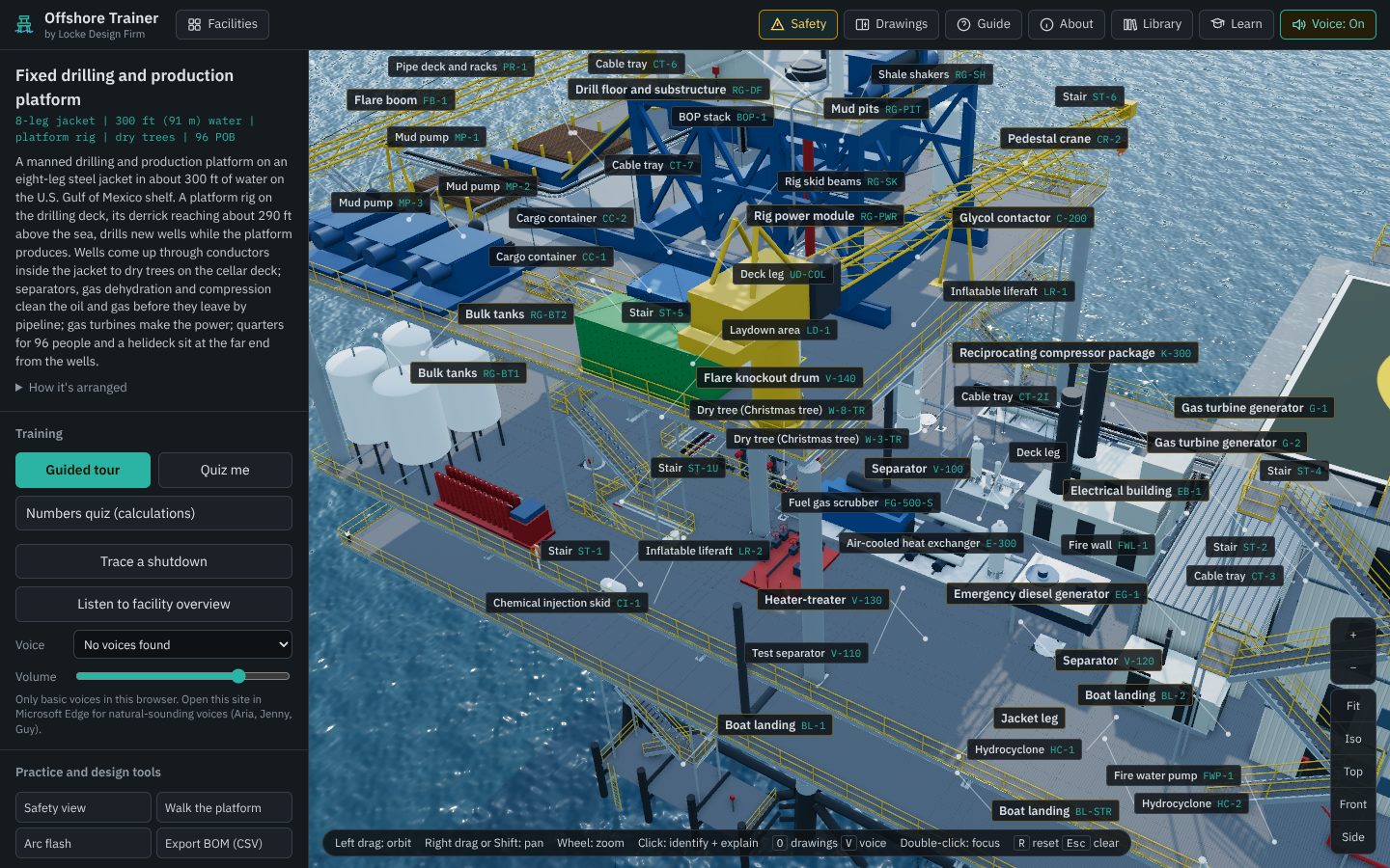
Know the platform before you zoom in
The platform is laid out the way most shelf platforms are: the wells at one end with the drilling rig above them, the process in the middle, power and quarters at the other end, with the flare boom reaching out past the well end so the flame is as far as possible from the people. Read How it's arranged in the side panel for the reasons, then orbit once around the platform to find:
- The jacket and piles standing in about 300 ft of water, with the conductors running down through the well bay.
- The cellar deck (lower) with the trees and the wellhead control panel, the separators, oil treating and export, and the produced-water treatment, and the main deck (middle) with gas dehydration and compression, the generators, the electrical building, the quarters and, at the well end, the rig's power module, BOP closing unit, choke manifold and bulk tanks.
- The drilling deck (top, over the well end) with the platform rig: the derrick and drill floor on skid beams over the well bay, the mud pits, shakers and pumps, the pipe deck and the cargo laydown. The BOP stack sits on the well being drilled, down on the cellar deck under the drill floor.
- The helideck on top of the four-level quarters, two cranes on the drilling deck, four lifeboats, two on each side, and the two boat landings at opposite corners.
X-ray: below the waterline
Turn on X-ray under Layers to make the sea and the decks see-through. You can then follow the jacket legs, braces and piles to the seabed, the conductors through their guide frames, the risers clamped to the legs, the anodes and the pipelines leaving along the seabed. Items that are below water or inside equipment say so in their info panel, and the library turns X-ray on for you when you go to one of them.
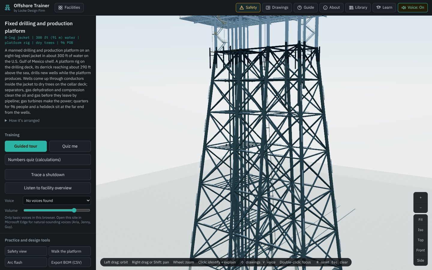
If the model feels slow
Set Quality under Layers to Balanced (full detail only when the view is still) or Fast (no shadows or ambient occlusion), and turn off Shadows. Turning off layers you are not using also helps. The setting is remembered.
Try it
- Press Top, then Iso, then R.
- Turn on Labels and zoom in on the main deck until the instrument tags appear.
- Turn on X-ray, orbit below the water and find a riser and its clamps on a jacket leg.
The platform's systems
Layers
Every item belongs to one layer. Untick a layer to hide it:
| Layer | What it holds |
|---|---|
| Equipment | Trees, vessels, pumps, compressors, packages and skids, the flare, cranes, cargo; the rig's top drive, drawworks, mud pumps, pits, shakers, bulk tanks and pipe racks |
| Process piping | Flowlines, headers, process and relief piping, manual, check and control valves, risers, pipelines and the pig launcher |
| Instruments & tubing | Transmitters, gauges, stands, impulse tubing, heated enclosures, the wellhead control panel and its control tubing, control panels |
| Electrical, cable & tray | Generators, switchgear, the MCC, transformers, batteries, the rig power module, cable tray, conduit and the cables in them |
| Safety systems | Surface safety valves, shutdown valves and relief valves; ESD stations, gas and flame detectors and the fusible loop; firewater, deluge and fire walls; lifeboats, life rafts, ring buoys and muster stations; the helideck; navigation lights and the fog signal; the BOP stack, its closing unit, the choke manifold and the mud gas separator |
| Structure & decks | Jacket, piles, conductors, deck legs, framing, grating, rails, stairs and skid bases; the derrick, drill floor and substructure, skid beams and catwalk |
| Buildings & quarters | The electrical building, the quarters and the driller's cabin |
| Sea, seabed & below water | The sea surface, the seabed, the water column, the boat landings, anodes and caissons |
Component catalog
The catalog at the bottom of the side panel lists every type of item on the platform, grouped by system: structure and marine, wells, drilling and well control, process vessels, rotating equipment, piping and valves, instruments, safety, electrical, cable and tray, lifting and accommodation. Type in the search box (separator, PSV, crane), then click a row to highlight every item of that type and open its info panel.
Equipment library
Library in the header opens every item in one place: a picture rendered from the model, what it is and does, typical ratings, the safety note, and the regulations and standards that cover it. See it in place takes you to the item on the platform. The library also has reference entries for things the model does not show, such as the subsurface safety valve deep in each well, personal protective equipment, test equipment and communications. Reference entries say so and carry no numbers.
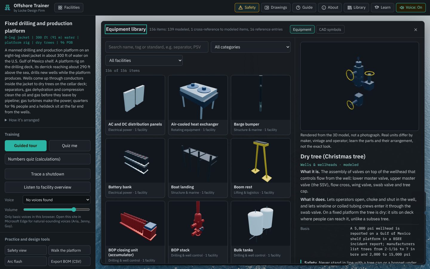
CAD symbols
The library's symbols tab holds the drawing symbols used on the sheets: process and instrument symbols drawn in the style of ISA-5.1 as commonly used on U.S. oil and gas drawings (valves, the SSV, SDV, BDV and PSV, pumps, compressors, vessels, instrument bubbles and signal lines), and electrical one-line symbols in the style of IEEE 315. Each symbol states its basis and downloads as a DXF block. Every operator keeps its own legend sheet, and that legend governs on real drawings.
The drawing set
Press Drawings or O. Pick a sheet from the list at the top of the pane. Click an item on a drawing to highlight it in 3D, and click an item in 3D to highlight it on the drawing. DXF exports the sheet on screen for CAD.
| Sheet | Shows |
|---|---|
| Process flow diagram | The well stream from the trees through separation, dehydration, compression, oil treating, export and produced water, with state points (pressure, temperature, rate; model values) |
| One-line | Power from the gas turbine generators through the switchgear and transformers (4,160 V on the fixed platform; 13.8 kV and 4,160 V on the TLP) to the motor control center, the emergency generator, the fire pumps, the UPS and the battery |
| Protection zones | The same one-line with the zone each protective device covers |
| Helideck, derrick and roof plan, and one plan per deck | Plans drawn from the 3D model with the structural grid (on the fixed platform the jacket legs, columns 1 to 4 and rows A and B; on the TLP the deck box grid, rows A to D), dimensions and tags. The fixed platform has drilling, main and cellar decks; the TLP has upper, main and lower decks |
| South elevation | The platform from the side, from the seabed to the flare, with deck elevations above mean lower low water |
| Jacket elevation (fixed platform) | The jacket framing levels, piles and conductor guides |
| Hull and tendon elevation (TLP) | The hull columns and pontoons, the tendons and their foundation piles, the production, drilling and export risers, drawn at one scale with the water column between the hull and the seabed left out |
| Cable schedule | Every circuit drawn in the model: source, load, cable or raceway, number of cables, the trays it runs in, and the length from terminal to terminal (tray route + drop + a 25 ft allowance). Download the cable schedule (CSV) sits under the sheet. |
| Legend | The symbols used on the set |
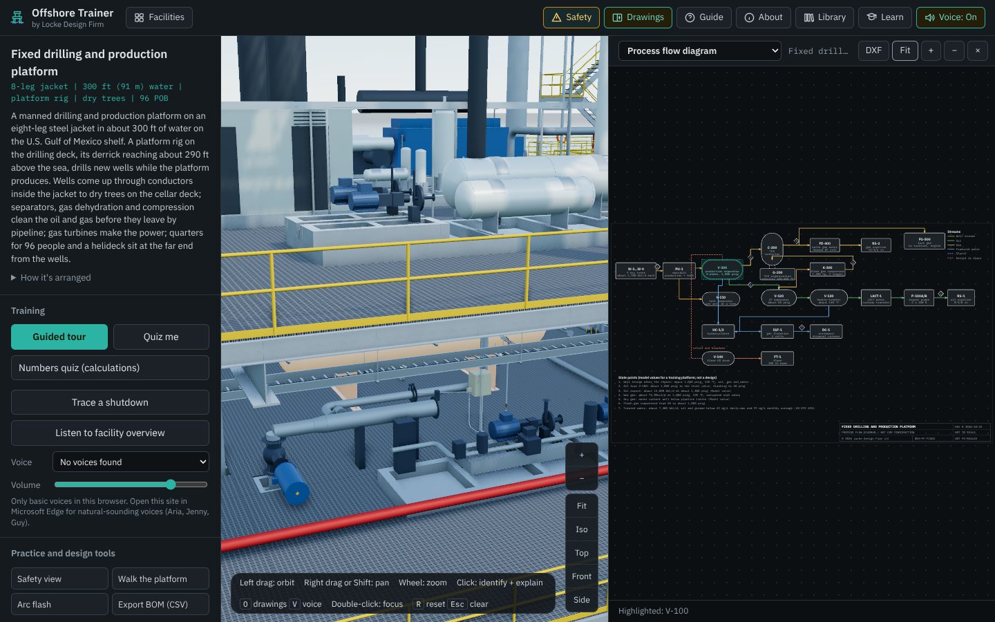
Title blocks say "NOT FOR CONSTRUCTION" and "NOT PE-SEALED". The sheets are generated from the training model to show how a drawing set is organized; they are not a design.
Try it
- Untick every layer except Structure & decks, then turn them back on one at a time.
- Open the library, search for tray, and use See it in place.
- Open the drawings, pick the main deck plan, and click the electrical building on the plan.
One process path
Guided tour
Guided tour walks you through 31 stops in the order the oil and gas move and the order you would learn the platform: the jacket and piles, the conductors, the platform rig (derrick, drill floor, BOP stack, closing unit, choke manifold, mud pumps and shakers), the wells and their safety valves, the manifold, the separator and its relief valve, the flare, dehydration and compression, oil treating and the LACT unit, the boarding shutdown valve, produced water, an instrument with its tubing, the cable trays, power, the ESD stations, the quarters, the lifeboats, the stairs and the cranes. Each stop highlights the item, frames it and explains it (spoken if the voice is on). Use Next and Back, or close the card to stop.
Trace a shutdown
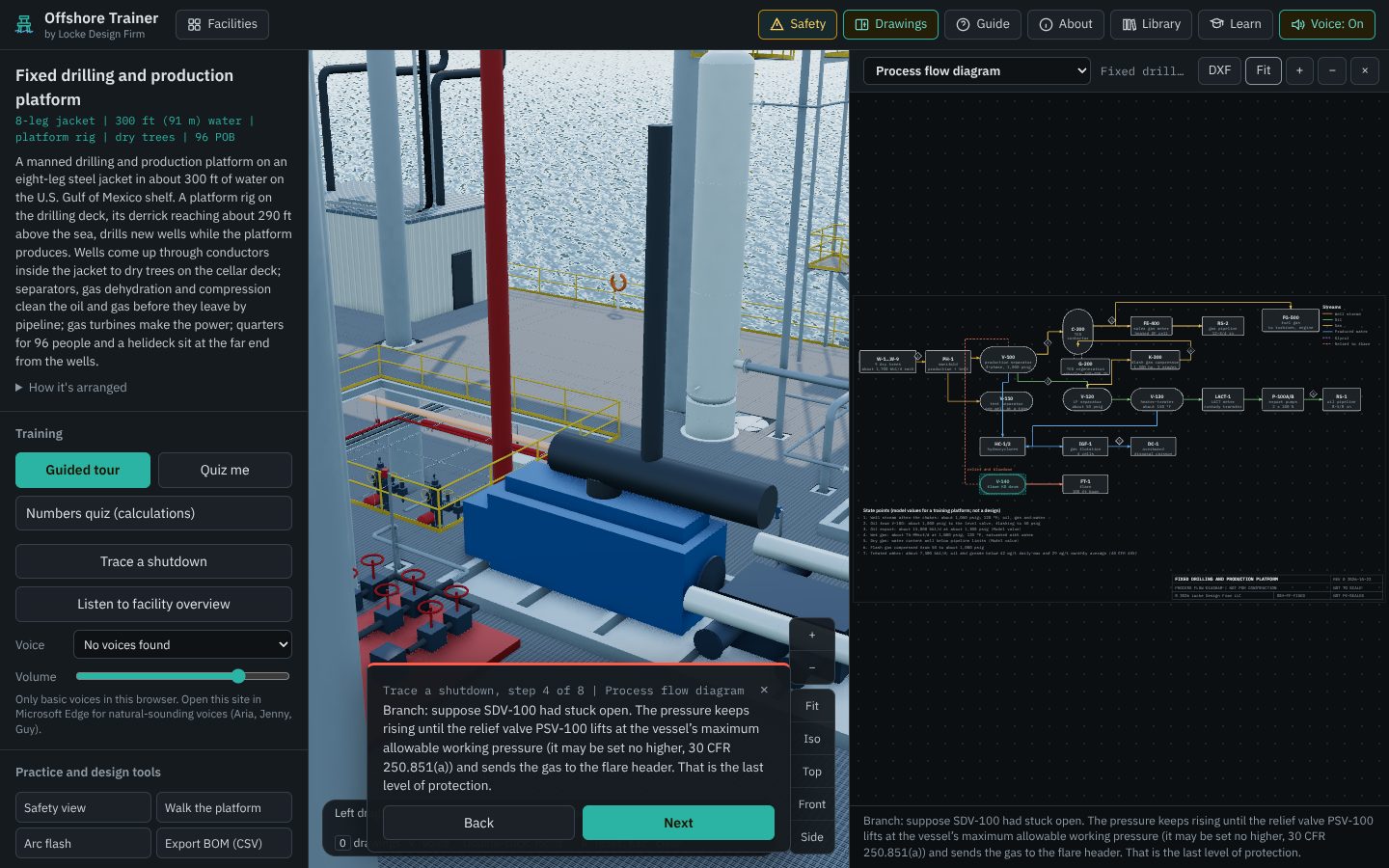
Trace a shutdown follows one upset from start to finish, with the drawing pane open beside the model: the separator's gas outlet is blocked, the pressure rises, the high-pressure sensor trips the inlet shutdown valve, the wells feeding it shut in, and, in a branch, the relief valve lifts to the flare. It then shows how a fire would raise the shutdown to the whole platform, how the general alarm works, and what the emergency generator picks up if the main power trips. Each step highlights the items involved on both the drawing and the model and quotes the rule that sets the timing or set point.
Try it
- Run the guided tour to the end.
- Run Trace a shutdown. At each step, find the highlighted item in 3D before you press Next.
One piece of equipment
Reading the info panel
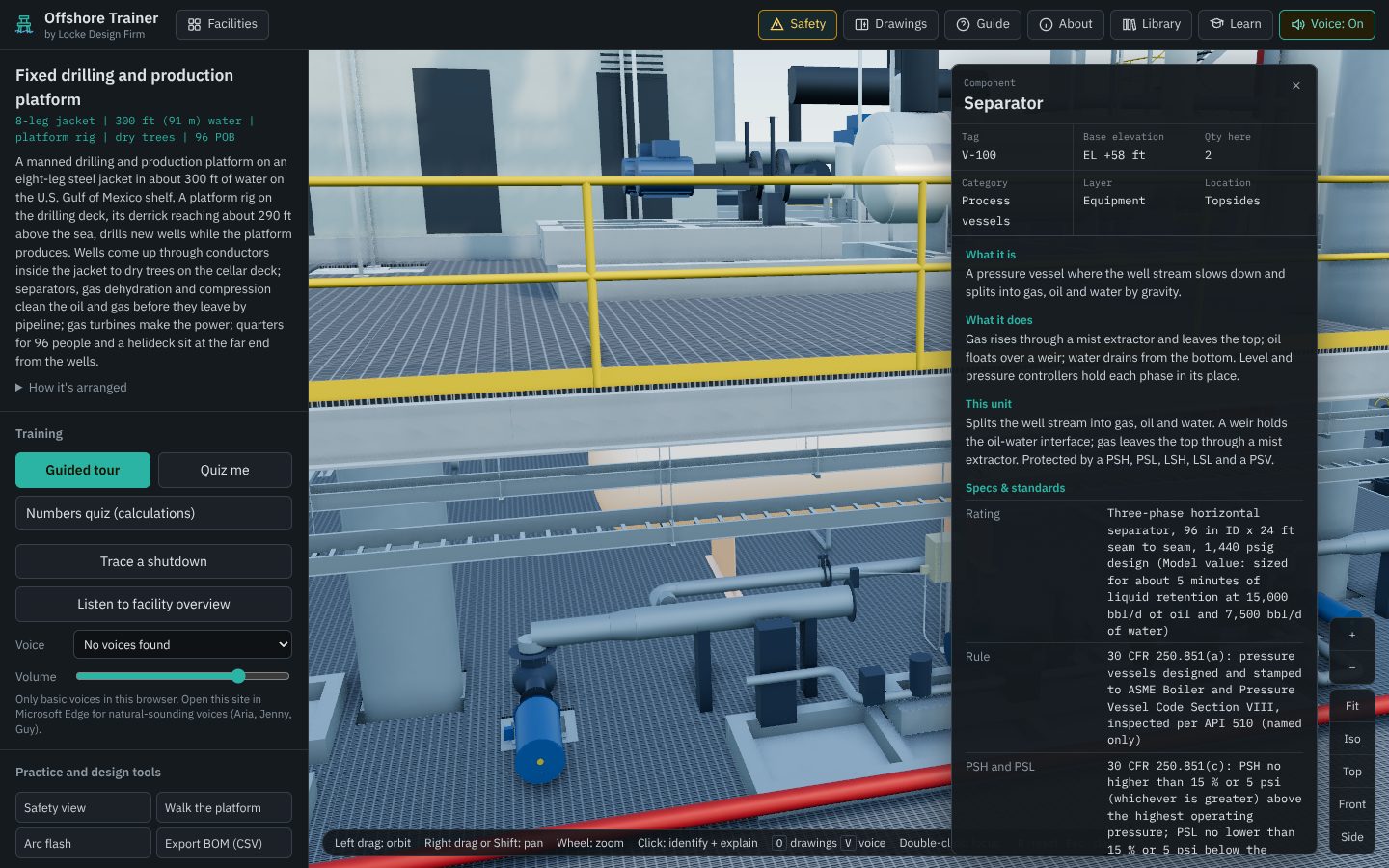
Click any item. The info panel opens on the right with:
- the name and tag, the base elevation above mean lower low water (or the voltage, for electrical items), how many of that item are on the platform, and the system it belongs to;
- What it is and what it does, in plain words;
- a table of ratings and sizes. Each value says what kind it is: a regulation (with the section), a standard named only, typical practice from a report or a maker's data, or a model value (see How to read the numbers);
- the safety note, and the safety card for that kind of equipment (level 6).
Panel buttons
| Button | Does |
|---|---|
| Listen | Reads the explanation aloud |
| Focus | Flies the camera to the item |
| Isolate / Show everything | Hides everything else so you can orbit the item on its own, then brings the rest back |
| Highlight all | Highlights every item of the same type on the platform |
| Library entry | Opens the item in the library with the codes and standards |
Instruments, tubing and cable
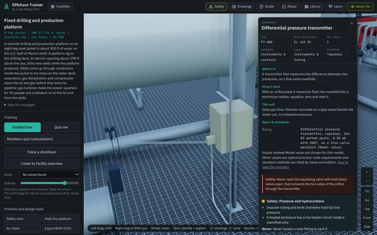
The model shows how field instruments are actually installed. A remote-mounted transmitter stands on a 2 in pipe stand with stainless impulse tubing sloped back to its taps, and the gas meter's transmitter sits in a heated enclosure. Cables run in aluminum ladder tray, with power and instrument cables in separate trays, and drop to motors and instruments in rigid aluminum conduit with a seal where the conduit enters the enclosure. Tubing never runs in an electrical tray. Click any of these items to see its size and where the size came from.
Voice settings
Choose a voice and volume under Training. Listen to facility overview reads a short introduction to the platform. Turn the voice off with the header button or V.
Try it
- Click a relief valve (PSV) and read where its set pressure rule comes from.
- Click the flow transmitter FT-400, then Isolate, and orbit around its stand and tubing.
- Click a cable tray and read its size and support spacing.
Safety
The Safety guide
Safety in the header opens the offshore safety guide. Its chapters are: Start here; Alarms, muster and abandon; Escape routes; Hydrogen sulfide (H2S); Fire, gas and the ESD; Permits, isolation and hot work; Working at height and over water; Lifting and dropped objects; SEMS: the safety management system; Earthing, bonding and lightning; PPE and confined spaces; the equipment safety cards; and a 13-question Safety check (pass mark 10). Each rule it states quotes the regulation it comes from, and the chapters link to the items on the platform.
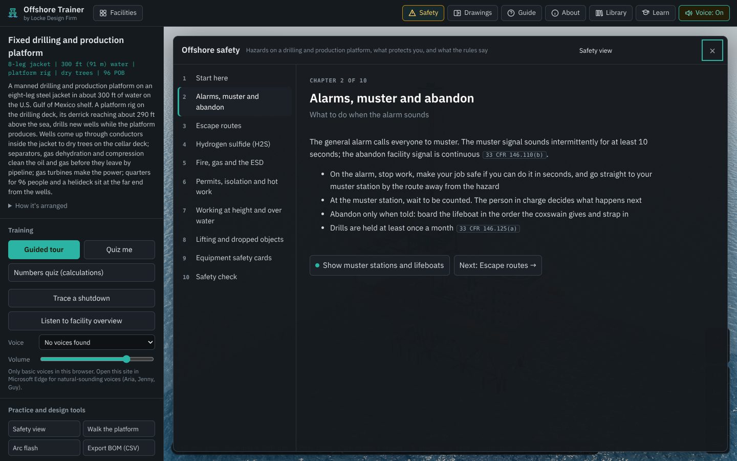
The guide is general. On a real facility, the operator's orientation, the station bill posted on board, the permit system and your supervisor govern.
Safety view
Safety view under Practice and design tools colors the platform by hazard family: pressure and hydrocarbons, fired and hot equipment, electrical, rotating equipment and noise, lifting and dropped objects, falls and working over water, and protective and lifesaving equipment. Click an item to see its safety card: what can hurt you, the controls and the rules behind them.
Walk the platform
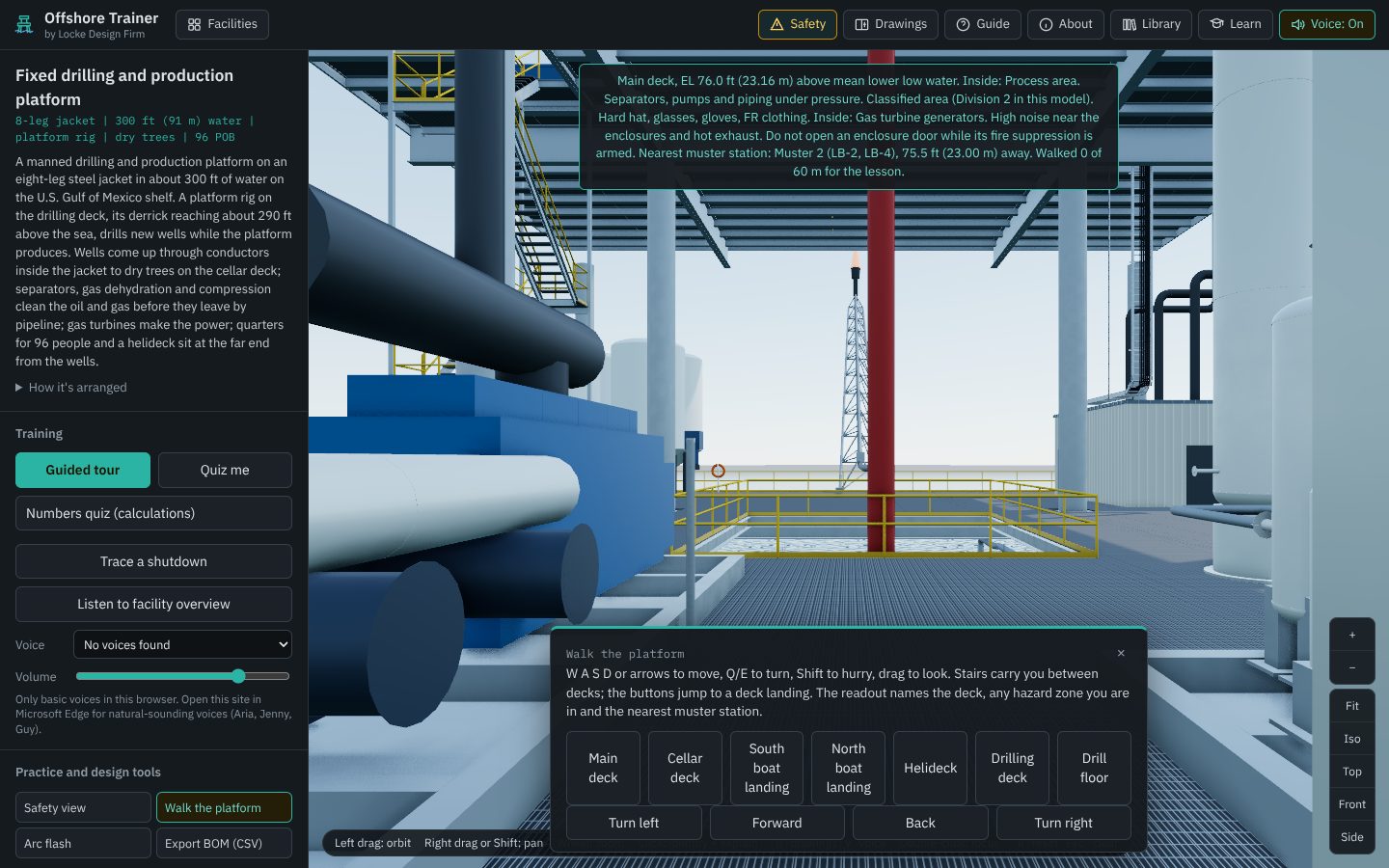
Walk the platform puts you on the main deck at eye level. Move with W A S D or the arrows, turn with Q and E, hold Shift to hurry and drag to look around. Stairs carry you between decks, and the buttons on the card jump to the main deck, the cellar deck, either boat landing, the helideck, the drilling deck or the drill floor. The readout names the deck you are on, any hazard zone you are in (classified areas, the compressor, the generators, the drill floor red zone, the mud pits and pumps, the pipe deck, the laydown area under the crane, the helideck, the boat landings, the flare end) and the nearest muster station.
Arc flash
Arc flash works the IEEE 1584-2002 equations for the platform's electrical gear, with presets for the 480 V gear, the 4,160 V switchgear and the TLP's 13.8 kV switchgear (fault currents and clearing times are model values). Move the sliders to see how fault current, clearing time and working distance change the incident energy and the arc-flash boundary, and see the label that results. It is a teaching model: real labels come from an arc flash study of the actual facility.
Try it
- Read the Alarms, muster and abandon chapter, then find the lifeboats on both sides of the platform.
- Turn on Safety view and click items from three different hazard families.
- Walk from the main deck down to a boat landing by the stairs, and note the hazard zones you pass.
Proving what you learned
Quiz me
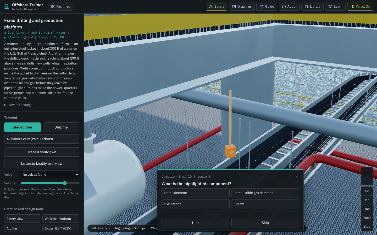
Quiz me asks ten questions about the platform. Some highlight an item and ask what it is; others ask what an item does. The choices are always similar items, so you have to know the difference rather than just recognize the category. Labels are hidden during the quiz, and Hint gives a nudge. Items you miss come back in later rounds until you get them right. A score of 8 or better counts toward the lessons.
Numbers quiz
Numbers quiz (calculations) asks eight questions with fresh values each round: hydrostatic pressure, kill mud weight, API gravity, barrels and cubic meters, gas-oil ratio, pressure units and motor full-load current. Each answer shows its working and the source of the constants. The well control questions are teaching exercises only; the well-specific plan and the well control procedures govern any real kill.
Lessons
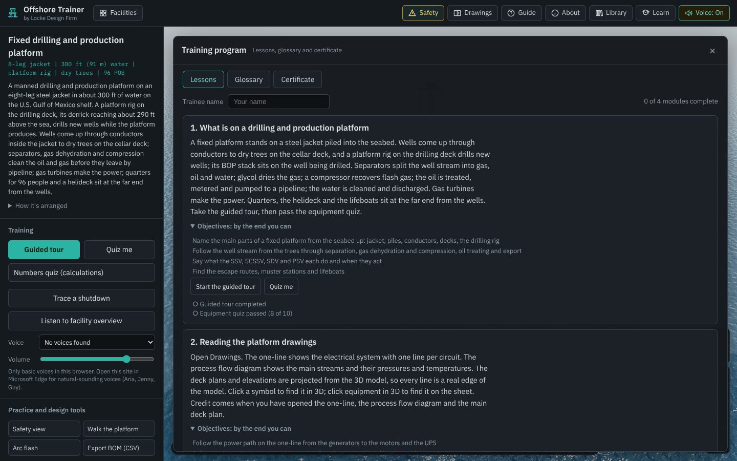
Press Learn in the header and enter the trainee's name. There are four modules. Each lists its objectives, has buttons that take you straight to the right tool, and checkmarks that fill in when you finish the activity:
| Module | To complete it |
|---|---|
| 1. What is on a drilling and production platform | Finish the guided tour, and score 8 of 10 on the quiz |
| 2. Reading the platform drawings | Open the one-line, the process flow diagram and the main deck plan |
| 3. Walking the platform | Walk 60 m on the decks |
| 4. Offshore safety basics | Score 10 of 13 on the Safety check at the end of the Safety guide, and click items from three different hazard families in Safety view |
Glossary
The Glossary tab explains the abbreviations used offshore (BSDV, ESD, LACT, MLLW, PSH and PSL, SCSSV, SSV, TSE and others) and every item in the trainer. Type to search it.
Certificate
When all four modules are complete, the Certificate tab prints an Offshore Trainer certificate with the trainee's name. Until then it lists the modules that are left. It records participation in a self-paced program; it is not an offshore orientation or any training an operator requires. Download my progress saves progress to a small file you can keep, show your trainer or load on another computer with Import progress. Reset my progress clears it, which is useful on a shared training computer.
Export BOM (CSV)
Export BOM (CSV) downloads a bill of materials for the platform built from the model. It opens in Excel with header rows (facility, date, basis, and a training-only, not-PE-sealed notice), then: Category, Item, Spec / rating, Qty, Unit, Quantity basis, Supplied as and Tags. Quantity basis says where each count comes from, for example counted in the model or a length measured along the tray.
Try it
- Take the quiz until you score 8 or better.
- Open Learn, enter your name, and see which checkmarks you already earned.
- Export the BOM and find the cable tray lengths in it.
Quick reference
Keyboard shortcuts
| Key | Does |
|---|---|
| O | Open or close the drawing pane |
| V | Voice on or off |
| R | Reset the camera |
| F | Focus on the selected item |
| Esc | Close an open window (library, Learn, Safety, Facilities menu), then leave the current tool, then clear the selection, stop the voice, or end the tour or quiz |
| Tab | Move through every button and control; everything in the side panel and dialogs works from the keyboard |
| W A S D / arrows, Q E, Shift | Move, turn and hurry while walking the platform |
A suggested plan for a new hire
| Session | Do |
|---|---|
| 1 (30 min) | Levels 1 and 2 of this guide; the guided tour; Quiz me until 8 of 10 |
| 2 (30 min) | The Safety guide, all chapters; Safety view; walk from the quarters to both lifeboats and both boat landings |
| 3 (30 min) | Trace a shutdown; the process flow diagram and the one-line; the Safety check |
| 4 (20 min) | The library for the equipment in the trainee's own job; the Numbers quiz; print the certificate |
If something isn't working
| Problem | Try |
|---|---|
| The model is slow or jerky | Set Quality to Balanced or Fast and turn off Shadows (level 2). |
| No voice, or a robotic voice | Use Microsoft Edge and pick a voice with "Natural" in the name. |
| I'm lost in the model | Press Fit or R. |
| Clicking an item does nothing | Finish or close the quiz first, or press Esc to leave the current tool. |
| Something is missing | Check the Layers checkboxes, and press Show everything if an item is isolated. |
| I can't see the jacket or the pipelines | They are under water: turn on X-ray. |
| My lesson progress is gone | Progress lives in the browser it was earned in. Use the same browser on the same computer, or move it with Download my progress and Import progress. |
| The library search finds nothing | Use one simple word, a tag letter group such as PSV or SDV, or a rule such as 250.851, and set the filters back to All. |
| I found a mistake in the model or a value | Use the report form on the About page. Every report is checked against the source. |