Offshore equipment reference
174 items: 157 modeled in the 3D facilities, 1 cross-reference to modeled items and 16 reference entries. What each one is, what it does, typical ratings, the safety note and the standards that cover it. Values are typical for training, not design values.
Open the trainerStructure & marine
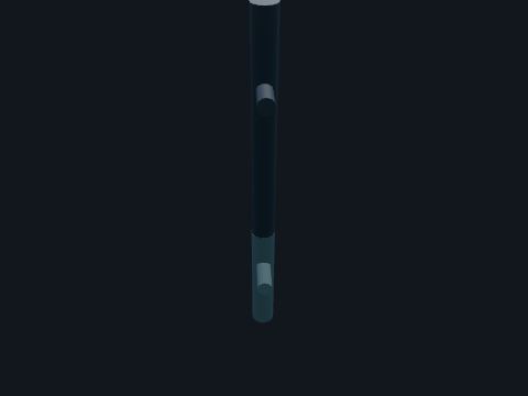
Barge bumper
A vertical tube held off a corner leg of the jacket. Takes the contact of a supply boat or barge so it does not strike the leg or a riser.
| Basis | Vertical bumper pipes of about 16 to 24 in on the legs are typical (model value) |
Standards: 30 CFR 250 Subpart I (platforms and structures), API RP 2A-WSD (fixed offshore platforms; 22nd ed. 2014, reaffirmed 2020, per 30 CFR 250.198)
Show it in 3D: Fixed platform × 2
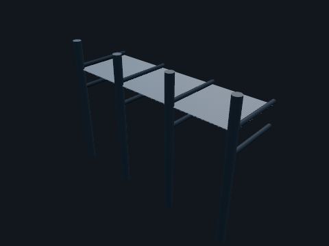
Boat landing
A small deck near the waterline with vertical bumper tubes, at two opposite corners of the jacket. Crew boats come alongside here to transfer people and small cargo. The vertical bumpers take the boat’s contact. The stairs from the decks end here, so the boat landings are also part of the escape route to the water.
| Basis | Gulf of Mexico platforms commonly have two boat landings at diagonal corners (USGS Open-File Report 81-712) |
| ESD | 30 CFR 250.855(a): ESD stations at the boat landing are the only ones allowed to use a loop of breakable synthetic tubing; where stations go is set by API RP 14C Appendix C (named only) |
Safety. Swing-rope and basket transfers are only done with the boat crew and platform crew in radio contact. Wear a work vest on the landing.
Standards: 30 CFR 250 Subpart I (platforms and structures), API RP 2A-WSD (fixed offshore platforms; 22nd ed. 2014, reaffirmed 2020, per 30 CFR 250.198), 33 CFR 143.105 (personnel landings)
Show it in 3D: Fixed platform × 3

Deck framing
The steel girders and beams of a deck: deep main girders over the leg rows, transverse girders at each leg, and lighter floor beams between. Carries the deck, the equipment and the people, and carries their weight to the deck legs. Equipment skids sit on the girders where possible.
Safety. Hot work on deck steel needs a permit and gas testing; steel under grating can hide trapped hydrocarbons in drip pans.
Standards: 30 CFR 250 Subpart I (platforms and structures), API RP 2A-WSD (fixed offshore platforms; 22nd ed. 2014, reaffirmed 2020, per 30 CFR 250.198), API RP 2SIM (structural integrity management; 1st ed. 2014, reaffirmed 2020, per 30 CFR 250.198), ISO 19902 (fixed steel offshore structures), AWS D1.1 (structural welding)
Show it in 3D: Fixed platform × 3Deepwater TLP × 4

Deck grating
Welded steel bar grating that forms the walking surface of open decks. Lets rain, wash water and spilled liquid drain to the drip pans below and lets gas leaks disperse instead of pooling. It also lets light and air through to the deck below.
Safety. Missing or loose grating panels are a fall hazard: barricade the opening before you lift a panel and never step on a panel you have not seen fixed down.
Standards: 30 CFR 250 Subpart I (platforms and structures), 33 CFR 142.87 (deck openings)
Show it in 3D: Fixed platform × 5Deepwater TLP × 5

Deck leg
The vertical tubes that carry the decks, set on top of the jacket legs. They lift the decks clear of the largest storm waves. The cellar deck is the lowest deck; its height above the sea is what kept platforms safe or lost them in the 2004 to 2008 hurricanes.
| Deck height | Bottom of steel of the cellar deck at +55 ft here. Hurricane hindcast crests of about 47 to 50 ft were reported at 250 to 320 ft of water (BSEE TA&R 642); decks below about 50 ft were the ones flooded (Model value) |
Standards: 30 CFR 250 Subpart I (platforms and structures), API RP 2A-WSD (fixed offshore platforms; 22nd ed. 2014, reaffirmed 2020, per 30 CFR 250.198), API RP 2SIM (structural integrity management; 1st ed. 2014, reaffirmed 2020, per 30 CFR 250.198), ISO 19902 (fixed steel offshore structures), AWS D1.1 (structural welding)
Show it in 3D: Fixed platform × 2Deepwater TLP × 2

Deck plate
Solid steel plate where equipment sits, with curbs to make a drip pan. Catches any oil or chemical that leaks from the equipment above so it goes to the drain system and the sump, not into the sea.
Safety. Plate gets slippery with oil and water; keep it clean and report leaks.
Standards: 30 CFR 250 Subpart I (platforms and structures)
Show it in 3D: Fixed platform × 1Deepwater TLP × 1
Disposal caisson
A large vertical pipe from the deck to below the sea surface. Treated produced water goes overboard through it, released below the surface.
Safety. A sheen on the water near the caisson is reported at once.
Standards: 40 CFR 435 Subpart A, NPDES general permit for the Gulf of Mexico OCS (named only)
Show it in 3D: Fixed platform × 1Deepwater TLP × 1

Jacket brace
The smaller tubes that tie the legs together: horizontal framing at each level and diagonal X-braces in each face between levels. Braces turn the legs into a stiff truss so wave loads go to the piles without bending the legs. X-braces cross at a joint; the horizontal framing at each level also carries the conductor guides and anodes.
| Basis | Brace sizes of 24 to 30 in OD were reported for an eight-leg jacket in 340 ft of water (BSEE TA&R 224) |
Safety. Damaged or flooded braces are found by underwater inspection; a missing brace changes how the whole jacket carries load.
Standards: 30 CFR 250 Subpart I (platforms and structures), API RP 2A-WSD (fixed offshore platforms; 22nd ed. 2014, reaffirmed 2020, per 30 CFR 250.198), API RP 2SIM (structural integrity management; 1st ed. 2014, reaffirmed 2020, per 30 CFR 250.198), ISO 19902 (fixed steel offshore structures), AWS D1.1 (structural welding)
Show it in 3D: Fixed platform × 1

Jacket leg
One of the large steel tubes at the corners and sides of the jacket, the welded steel frame that stands on the seabed and holds the decks above the waves. The legs carry the weight of the decks down to the piles and, with the braces, resist the push of waves, current and wind. They lean outward going down (the batter) so the base is wider than the top. Each leg is a sleeve for a pile driven down through it.
| Basis | Eight-leg Gulf of Mexico jackets in 270 to 340 ft of water reported 44-3/4 to 54 in OD legs battered 1:8 to 1:10 (BSEE TA&R 202, 224) |
Safety. Below water the legs are inspected by divers or ROVs for dents, cracks and flooded members. Above water they are fall-protection anchor points only where an engineer has rated them.
Standards: 30 CFR 250 Subpart I (platforms and structures), API RP 2A-WSD (fixed offshore platforms; 22nd ed. 2014, reaffirmed 2020, per 30 CFR 250.198), API RP 2SIM (structural integrity management; 1st ed. 2014, reaffirmed 2020, per 30 CFR 250.198), ISO 19902 (fixed steel offshore structures), AWS D1.1 (structural welding)
Show it in 3D: Fixed platform × 1

Mudmat
Steel plates on the bottom framing of the jacket. They spread the jacket’s weight on soft seabed mud so it does not sink before the piles are driven.
Standards: 30 CFR 250 Subpart I (platforms and structures), API RP 2A-WSD (fixed offshore platforms; 22nd ed. 2014, reaffirmed 2020, per 30 CFR 250.198), API RP 2SIM (structural integrity management; 1st ed. 2014, reaffirmed 2020, per 30 CFR 250.198), ISO 19902 (fixed steel offshore structures), AWS D1.1 (structural welding)
Show it in 3D: Fixed platform × 1

Pile
A steel pipe driven through each jacket leg deep into the seabed, then fixed to the top of the leg. Piles anchor the platform: they carry its weight down into the soil and stop it sliding or overturning in a storm. The gap between pile and leg is often filled with grout so the two act together.
| Basis | 48 in piles driven 180 to 285 ft were reported for eight-leg jackets in 213 to 340 ft of water (BSEE TA&R 202, 224) |
Standards: 30 CFR 250 Subpart I (platforms and structures), API RP 2A-WSD (fixed offshore platforms; 22nd ed. 2014, reaffirmed 2020, per 30 CFR 250.198), API RP 2SIM (structural integrity management; 1st ed. 2014, reaffirmed 2020, per 30 CFR 250.198), ISO 19902 (fixed steel offshore structures), AWS D1.1 (structural welding)
Show it in 3D: Fixed platform × 1
Pump caisson
A large pipe hanging from the deck down below the sea surface. Protects a long vertical pump column from waves and holds its suction under water at all tides.
Standards: 30 CFR 250 Subpart I (platforms and structures), API RP 2A-WSD (fixed offshore platforms; 22nd ed. 2014, reaffirmed 2020, per 30 CFR 250.198)
Show it in 3D: Fixed platform × 2Deepwater TLP × 2
Sacrificial anode
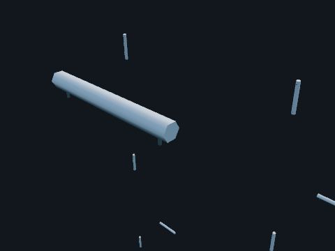
Blocks of aluminum alloy cast on steel cores, welded to the jacket below the splash zone. Cathodic protection: the anodes corrode instead of the jacket steel. Divers or ROVs measure the protection potential and the anodes’ remaining size at each inspection.
Standards: NACE (AMPP) SP0176 (cathodic protection of fixed offshore steel platforms), API RP 2A-WSD
Show it in 3D: Fixed platform × 1
Sea surface
The open water around the facility, drawn at mean lower low water (MLLW), the chart datum for U.S. waters. Every elevation on this site is measured from MLLW: deck heights, the splash zone and the water depth. Turn on X-ray to see below the waterline.
Show it in 3D: Fixed platform × 1Deepwater TLP × 1
Seabed (mudline)
The sea floor at the foot of the structure. Offshore drawings call it the mudline. Piles and well conductors are driven or drilled through it. In X-ray the seabed and the soil below it turn see-through so you can see how far the piles go down.
Show it in 3D: Fixed platform × 1Deepwater TLP × 1
Skid base
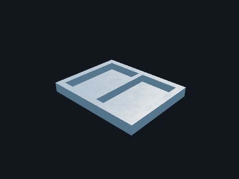
A welded steel frame with a drip pan that carries a package. Lets a package be built and tested onshore and lifted on as one piece; the drip pan drains to the platform drain system.
Standards: 30 CFR 250 Subpart I (platforms and structures), API RP 2A-WSD (fixed offshore platforms; 22nd ed. 2014, reaffirmed 2020, per 30 CFR 250.198)
Show it in 3D: Fixed platform × 2Deepwater TLP × 2
Stair
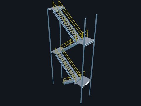
Steel stairs with grating treads and landings at every turn. Two stairs at opposite corners connect every deck and run down to the boat landings. They are the primary means of escape: if one is blocked by fire you use the other.
| Rule | 33 CFR 143.101(c), (f): a manned platform has at least two primary means of escape, fixed metal stairs or ladders, from each working level to each lower level and to the water surface, as nearly diagonally opposite each other as practicable |
Safety. Hold the handrail. In an emergency walk, do not run, and use the stair away from the fire or gas.
Standards: 33 CFR 143.101 (means of escape), 33 CFR 143.110 (guards and rails), 33 CFR 142.42 (safety belts and lifelines; fall hazard of 10 ft or more), 29 CFR 1910.25 (stairways; general industry, for comparison)
Show it in 3D: Fixed platform × 8Deepwater TLP × 6

Sump pile
A vertical pipe hung from the lowest deck down below the sea surface, open at the bottom. Deck drains and the flare knockout drum drain into it. Oil floats to the top and is held there while water leaves through the open bottom, well below the surface.
| Rule | 30 CFR 250.300(b)(4): oil drainage is piped to a sump system that keeps the oil at a level that prevents discharge; gravity drains have a water trap or other means so sump gas cannot escape through them |
Safety. A sheen on the water near the pile is reported at once.
Standards: 30 CFR 250.300(b)(4) (deck drains and the sump system), 40 CFR 435 Subpart A (offshore discharges)
Show it in 3D: Fixed platform × 1Deepwater TLP × 1

Vessel platform
A small grating platform with guard rails at the top of a tall vessel. Gives access to the top nozzles, relief valve and instruments.
Safety. Climbing the ladder to it is a fall-protection task: three points of contact and nothing in your hands.
Standards: 33 CFR 143.110 (guards and rails), 33 CFR 142.42 (safety belts and lifelines; fall hazard of 10 ft or more)
Show it in 3D: Fixed platform × 1Deepwater TLP × 1
Water column
The water between the sea surface and the seabed, shown as a tinted cutaway volume in X-ray. Shows how deep the structure goes and what is underwater: jacket legs and braces, piles, conductors, risers and anodes.
Show it in 3D: Fixed platform × 1Deepwater TLP × 1
Wells & wellheads

Conductor guide framing
Beams across the well bay at each jacket level, with a short sleeve at every well slot. The sleeves are a little larger than the conductors so the conductors can be run through them, and they hold the conductors against wave and current loads. Spare slots keep their sleeves ready for future wells.
| First level | The first guide framing below water is between -20 and -40 ft on many Gulf platforms (BSEE TA&R 549) |
Standards: 30 CFR 250 Subpart I (platforms and structures), API RP 2A-WSD (fixed offshore platforms; 22nd ed. 2014, reaffirmed 2020, per 30 CFR 250.198), API RP 2SIM (structural integrity management; 1st ed. 2014, reaffirmed 2020, per 30 CFR 250.198), ISO 19902 (fixed steel offshore structures), AWS D1.1 (structural welding)
Show it in 3D: Fixed platform × 1
Dry tree (Christmas tree)
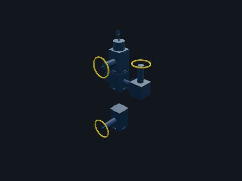
The assembly of valves on top of the wellhead that controls flow from the well: lower master valve, upper master valve (the SSV), flow cross, wing valve, swab valve and tree cap. Lets operators open, choke and shut in the well, and lets wireline or coiled tubing crews enter it through the swab valve. On a fixed platform the tree is dry: it sits on deck where people can reach it, unlike a subsea tree.
| Basis | A 5,000 psi wellhead is reported on a Gulf of Mexico shelf platform in a BSEE incident report; manufacturers list trees from 2-1/16 to 7 in bore and 2,000 to 15,000 psi |
Safety. Never stand in line with a tree cap or a bonnet under pressure. Valves are operated in a set order: master valves are opened first and closed last so the wing valve takes the wear.
Standards: 30 CFR 250.810-250.821 (subsurface and surface safety devices), API Spec 6A (wellhead and tree equipment; 21st ed. 2018 with errata and addenda, per 30 CFR 250.198), API Std 6AV1 (SSV/USV validation; 3rd ed. 2018, per 30 CFR 250.198), API Std 6AV2 (SSV/USV installation, maintenance and repair)
Show it in 3D: Fixed platform × 9Deepwater TLP × 12
Production choke
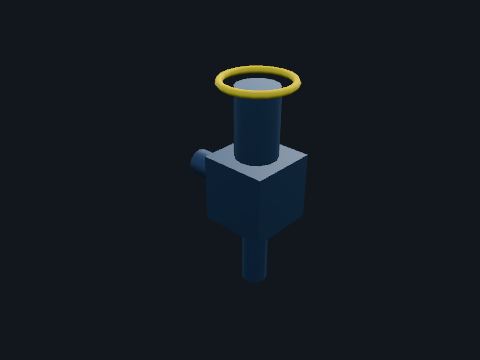
An adjustable valve with a tapered seat in the wing of the tree. Sets the flow rate of the well by taking most of the pressure drop. The gas that expands through it gets colder, which is where hydrates can form.
Safety. The choke and the line just after it erode fastest and can be cold enough to freeze skin. A choke is not a shutoff: never use it to isolate.
Standards: API Spec 6A (wellhead and tree equipment; 21st ed. 2018 with errata and addenda, per 30 CFR 250.198)
Show it in 3D: Fixed platform × 9Deepwater TLP × 12
Subsurface safety valve (SCSSV)
A fail-closed valve in the production tubing, set below the mudline and held open by hydraulic pressure from the wellhead control panel through a small control line. Closes the well below the seabed if the surface equipment is lost or the control pressure is bled off by the ESD or fire loop. It is the last barrier when the tree itself is damaged.
Standards: 30 CFR 250.814 (subsurface safety devices), 30 CFR 250.821 (closure timing), API Spec 14A (subsurface safety valve equipment; 11th ed. 2005, reaffirmed 2012, per 30 CFR 250.198), API RP 14B (SSSV systems; named only)
Reference entry, not built in a facility yet
Surface safety valve (SSV)
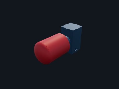
An actuated gate valve in the tree, held open by control pressure and closed by a spring when that pressure is vented. The automatic shut-in valve for the well. Every process shutdown and the ESD vent its control line through the wellhead control panel, and it closes.
| Closing time | 30 CFR 250.821(b): closure of the SSV must not exceed 45 seconds after automatic detection of an abnormal condition or actuation of an ESD |
| Testing | 30 CFR 250.880(c)(2)(iv): once each calendar month, not to exceed 6 weeks between tests |
| Failure | 30 CFR 250.820: a failed SSV or observed leakage means shutting in all sources to it and repairing or replacing it before production resumes |
Safety. Never pin open or gag an SSV. A bypassed safety device must be flagged and monitored (30 CFR 250.869).
Standards: 30 CFR 250.810-250.821 (subsurface and surface safety devices), API Spec 6A (wellhead and tree equipment; 21st ed. 2018 with errata and addenda, per 30 CFR 250.198), API Std 6AV1 (SSV/USV validation; 3rd ed. 2018, per 30 CFR 250.198), API Std 6AV2 (SSV/USV installation, maintenance and repair), 30 CFR 250.880(c)(2)(iv) (monthly testing)
Show it in 3D: Fixed platform × 9Deepwater TLP × 12

Well conductor
A large steel pipe from the seabed up to the cellar deck, one for each well slot. The first and largest string of pipe in the well. It keeps the soft seabed from caving in while the well is drilled, carries the weight of the wellhead and the casing strings hung inside it, and is held in line by guides at every jacket level.
Safety. Conductors are pressure barriers only after the casing inside them is cemented; never treat an open conductor as a safe hole to work over.
Standards: 30 CFR 250 Subpart I (platforms and structures), API RP 2A-WSD (fixed offshore platforms; 22nd ed. 2014, reaffirmed 2020, per 30 CFR 250.198), API RP 2SIM (structural integrity management; 1st ed. 2014, reaffirmed 2020, per 30 CFR 250.198), ISO 19902 (fixed steel offshore structures), AWS D1.1 (structural welding), 30 CFR 250 Subpart D (drilling)
Show it in 3D: Fixed platform × 1
Wellhead
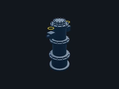
The stack of heavy steel spools on top of the conductor: casing head, casing spool and tubing head. Each casing string hangs from its own head and each annulus between strings is sealed off. Side outlets let operators read and bleed annulus pressure; the tubing hangs from the tubing head with the downhole safety valve control line passing through it.
| Rule | 30 CFR 250.802(a): SSVs and their actuators meet API Spec 6A and API Std 6AV1 (named only) |
Safety. Sustained pressure on an annulus that should be dead is reported and investigated; never bleed an annulus without the procedure for it.
Standards: 30 CFR 250.810-250.821 (subsurface and surface safety devices), API Spec 6A (wellhead and tree equipment; 21st ed. 2018 with errata and addenda, per 30 CFR 250.198), API Std 6AV1 (SSV/USV validation; 3rd ed. 2018, per 30 CFR 250.198), API Std 6AV2 (SSV/USV installation, maintenance and repair)
Show it in 3D: Fixed platform × 10Deepwater TLP × 12
Process vessels
Burner and flame arrestor
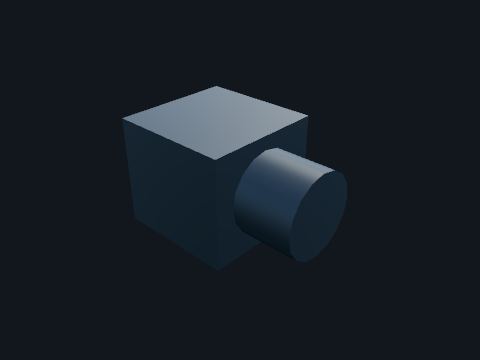
The burner that fires a firetube, with a flame arrestor on its air intake. The arrestor stops a flame inside the firetube from flashing back out through the air intake into gas outside.
Standards: 30 CFR 250.880(c)(3)(vi), (viii) (burner safety low; flame arrestors), API Spec 12K (indirect-type oil field heaters)
Show it in 3D: Fixed platform × 1
Electrostatic treater
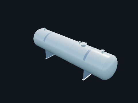
A large horizontal vessel with energized steel grids inside, fed with warmed oil. The electric field between the grids makes the small water droplets left in the oil merge and settle, so the oil leaving it meets the water limit for the pipeline. It is a pressure vessel with its own level and pressure trips.
| Rule | 30 CFR 250.851(a): pressure vessels designed and stamped to ASME Boiler and Pressure Vessel Code Section VIII (named only) |
Safety. The grids run at high voltage: the transformer on top is locked out and the vessel isolated before anyone opens a manway.
Standards: 30 CFR 250.851 (pressure vessels and fired vessels), ASME Boiler and Pressure Vessel Code Section VIII, API 510 (pressure vessel inspection), API RP 14C (surface safety systems; 7th ed. 2001, reaffirmed 2007, per 30 CFR 250.198), API RP 14J (design and hazards analysis; 2nd ed. 2001, reaffirmed 2013, per 30 CFR 250.198)
Show it in 3D: Deepwater TLP × 1
Exhaust stack
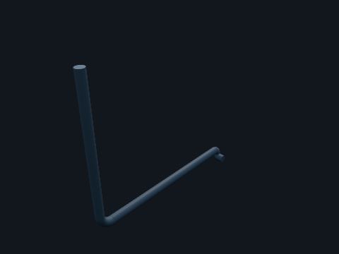
The stack on a fired vessel or engine. Carries hot exhaust up and away from the deck.
Safety. Stacks are hot enough to burn; exhaust can carry carbon monoxide.
Standards: 30 CFR 250.856 (engines; spark arresters), API RP 14C
Show it in 3D: Fixed platform × 3Deepwater TLP × 2
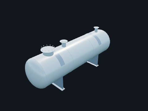
Flare knockout drum
A large horizontal vessel at the bottom of the flare system. Relief and blowdown flows slow down here so liquid drops out before the gas goes up to the flare tip.
| Basis | Sizing follows API Std 521 (named only) |
Safety. A high liquid level in the drum is a shutdown: liquid carried to the flare can fall back burning.
Standards: 30 CFR 250.851 (pressure vessels and fired vessels), ASME Boiler and Pressure Vessel Code Section VIII, API 510 (pressure vessel inspection), API RP 14C (surface safety systems; 7th ed. 2001, reaffirmed 2007, per 30 CFR 250.198), API RP 14J (design and hazards analysis; 2nd ed. 2001, reaffirmed 2013, per 30 CFR 250.198), API Std 521 (pressure-relieving and depressuring systems)
Show it in 3D: Fixed platform × 1Deepwater TLP × 1
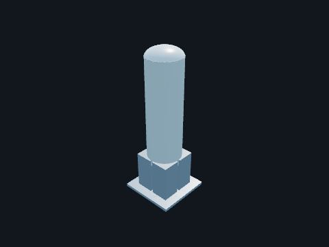
Fuel gas filter
A cartridge filter on the fuel gas skid. Removes particles that would wear the turbine fuel nozzles.
Standards: 30 CFR 250.851 (pressure vessels and fired vessels), ASME Boiler and Pressure Vessel Code Section VIII
Show it in 3D: Fixed platform × 2Deepwater TLP × 2
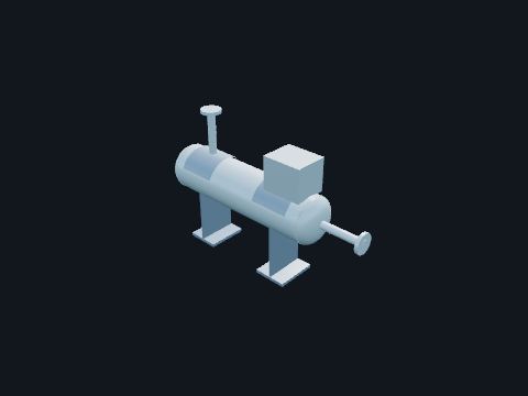
Fuel gas heater
A small electric heater on the fuel gas skid. Keeps the fuel gas a few degrees above its dew point so no liquid forms downstream.
Standards: 30 CFR 250.851 (pressure vessels and fired vessels), ASME Boiler and Pressure Vessel Code Section VIII
Show it in 3D: Fixed platform × 1Deepwater TLP × 1
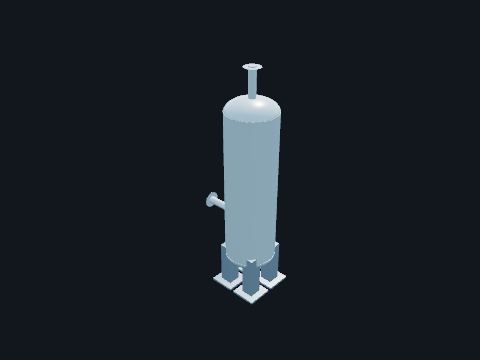
Fuel gas scrubber
A small vertical scrubber on the fuel gas skid. Removes liquid from the fuel gas before it reaches the turbines, the compressor engine and the burners.
Standards: 30 CFR 250.851 (pressure vessels and fired vessels), ASME Boiler and Pressure Vessel Code Section VIII, API 510 (pressure vessel inspection), API RP 14C (surface safety systems; 7th ed. 2001, reaffirmed 2007, per 30 CFR 250.198), API RP 14J (design and hazards analysis; 2nd ed. 2001, reaffirmed 2013, per 30 CFR 250.198)
Show it in 3D: Fixed platform × 1Deepwater TLP × 1
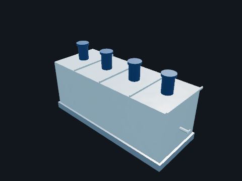
Gas flotation unit
A rectangular tank with four cells, each with a rotor that whips fine gas bubbles into the water. The bubbles carry the last oil droplets to the surface, where they are skimmed off, so the water can go overboard within the discharge limit.
| Rule | 40 CFR 435 (best available technology): oil and grease in produced water discharged offshore no more than 42 mg/L daily maximum and 29 mg/L average of daily values over 30 consecutive days |
Safety. The gas blanket in the cells is flammable; the cells are classified areas.
Standards: 30 CFR 250.851 (pressure vessels and fired vessels), ASME Boiler and Pressure Vessel Code Section VIII, 40 CFR 435 Subpart A
Show it in 3D: Fixed platform × 1Deepwater TLP × 1
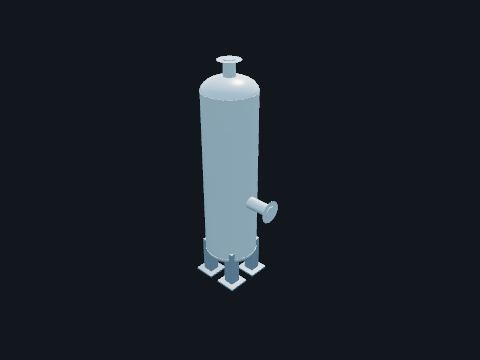
Gas scrubber
A vertical vessel with a mist pad ahead of a compressor. Catches liquid in the gas so no slug reaches the compressor cylinders.
| Rule | 30 CFR 250.858(a)(1): compressor suction scrubbers have a PSH, PSL, PSV, LSH and LSL |
Standards: 30 CFR 250.851 (pressure vessels and fired vessels), ASME Boiler and Pressure Vessel Code Section VIII, API 510 (pressure vessel inspection), API RP 14C (surface safety systems; 7th ed. 2001, reaffirmed 2007, per 30 CFR 250.198), API RP 14J (design and hazards analysis; 2nd ed. 2001, reaffirmed 2013, per 30 CFR 250.198), 30 CFR 250.858 (gas compressors)
Show it in 3D: Fixed platform × 1Deepwater TLP × 1
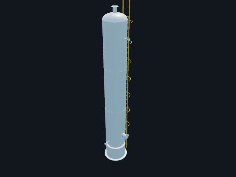
Glycol contactor
A tall vertical tower with bubble-cap trays where wet gas meets lean triethylene glycol (TEG). Glycol soaks up the water vapor in the gas so the gas will not form hydrates or corrode the pipeline. Wet (rich) glycol leaves the bottom for regeneration.
| Rule | 30 CFR 250.857: a flow safety valve on the dry glycol inlet and a shutdown valve on the wet glycol outlet of the contact tower |
| Typical | 6 to 12 trays at 24 in spacing; 500 to 1,200 psi is the most economical range (university course notes) |
Safety. Hot glycol and its vapors burn. The tower has a ladder and a top platform with rails: use fall protection rules for the climb.
Standards: 30 CFR 250.851 (pressure vessels and fired vessels), ASME Boiler and Pressure Vessel Code Section VIII, API 510 (pressure vessel inspection), API RP 14C (surface safety systems; 7th ed. 2001, reaffirmed 2007, per 30 CFR 250.198), API RP 14J (design and hazards analysis; 2nd ed. 2001, reaffirmed 2013, per 30 CFR 250.198), 30 CFR 250.857 (glycol dehydration units)
Show it in 3D: Fixed platform × 1Deepwater TLP × 1
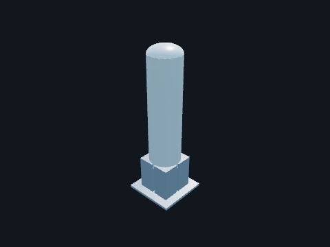
Glycol filter
Small filter housings on the glycol skid. Remove solids and dissolved hydrocarbons that would foul the glycol and the reboiler.
Safety. Spent charcoal and filter socks can hold hydrocarbons and benzene; handle them as the waste procedure says.
Standards: 30 CFR 250.851 (pressure vessels and fired vessels), ASME Boiler and Pressure Vessel Code Section VIII
Show it in 3D: Fixed platform × 2Deepwater TLP × 2
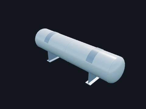
Glycol reboiler
A fired vessel that heats rich glycol to boil off the water it absorbed. Turns rich glycol back into lean glycol. A burner in a firetube heats it; the steam leaves through the still column.
| Typical | Reboiler 340 to 400 °F; above about 400 °F TEG begins to break down (university course notes) |
| Testing | 30 CFR 250.880(c)(3)(vi): burner safety low tested annually |
Safety. A fired vessel near hydrocarbons: the air intake has a flame arrestor (inspected annually, 30 CFR 250.880(c)(3)(viii)) and the burner shuts down on flame failure.
Standards: 30 CFR 250.851 (pressure vessels and fired vessels), ASME Boiler and Pressure Vessel Code Section VIII, API 510 (pressure vessel inspection), API RP 14C (surface safety systems; 7th ed. 2001, reaffirmed 2007, per 30 CFR 250.198), API RP 14J (design and hazards analysis; 2nd ed. 2001, reaffirmed 2013, per 30 CFR 250.198), 30 CFR 250.880(c)(3)(vi), (viii) (burner safety low; flame arrestors), API Spec 12K (indirect-type oil field heaters), 30 CFR 250.857
Show it in 3D: Fixed platform × 1Deepwater TLP × 1
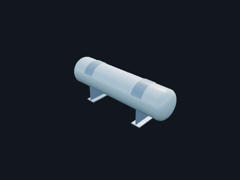
Glycol surge drum
A small horizontal tank holding lean glycol. Stores lean glycol ahead of the circulation pumps and cools it through a heat exchanger.
Standards: 30 CFR 250.851 (pressure vessels and fired vessels), ASME Boiler and Pressure Vessel Code Section VIII
Show it in 3D: Fixed platform × 1Deepwater TLP × 1
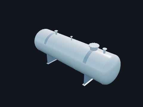
Heater-treater
A horizontal vessel with a fired firetube, used to break oil and water emulsion. Warms the oil so water droplets drop out, then settles them; treated oil leaves the top of the oil section and water leaves the bottom.
| Testing | 30 CFR 250.880(c)(3)(iv), (vi) and (viii): TSH annually, burner safety low annually, flame arrestors inspected annually |
Safety. Fired vessel: never light the burner without the purge and gas test the procedure calls for.
Standards: 30 CFR 250.851 (pressure vessels and fired vessels), ASME Boiler and Pressure Vessel Code Section VIII, API 510 (pressure vessel inspection), API RP 14C (surface safety systems; 7th ed. 2001, reaffirmed 2007, per 30 CFR 250.198), API RP 14J (design and hazards analysis; 2nd ed. 2001, reaffirmed 2013, per 30 CFR 250.198), 30 CFR 250.880(c)(3)(vi), (viii) (burner safety low; flame arrestors), API Spec 12K (indirect-type oil field heaters)
Show it in 3D: Fixed platform × 1
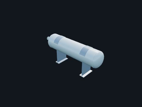
Hydrocyclone
A vessel holding many small cone-shaped liners. Spins the produced water so oil droplets move to the center and leave with a small reject stream. No moving parts: the pressure drop does the work.
| Typical | 10 to 25 mm liners, feed at about 150 psig (published Gulf of Mexico produced-water practice) |
Standards: 30 CFR 250.851 (pressure vessels and fired vessels), ASME Boiler and Pressure Vessel Code Section VIII, 40 CFR 435 Subpart A (offshore discharges)
Show it in 3D: Fixed platform × 2Deepwater TLP × 2
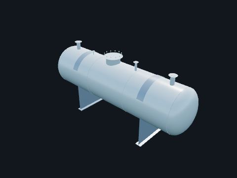
Separator
A pressure vessel where the well stream slows down and splits into gas, oil and water by gravity. Gas rises through a mist extractor and leaves the top; oil floats over a weir; water drains from the bottom. Level and pressure controllers hold each phase in its place.
| Rule | 30 CFR 250.851(a): pressure vessels designed and stamped to ASME Boiler and Pressure Vessel Code Section VIII, inspected per API 510 (named only) |
| PSH and PSL | 30 CFR 250.851(c): PSH no higher than 15 % or 5 psi (whichever is greater) above the highest operating pressure; PSL no lower than 15 % or 5 psi below the lowest |
| PSV | 30 CFR 250.851(a): set no higher than the vessel’s maximum allowable working pressure |
Safety. A separator holds a large inventory of gas and oil. Opening one for entry needs isolation with blinds, purging, gas testing and a confined space permit.
Standards: 30 CFR 250.851 (pressure vessels and fired vessels), ASME Boiler and Pressure Vessel Code Section VIII, API 510 (pressure vessel inspection), API RP 14C (surface safety systems; 7th ed. 2001, reaffirmed 2007, per 30 CFR 250.198), API RP 14J (design and hazards analysis; 2nd ed. 2001, reaffirmed 2013, per 30 CFR 250.198)
Show it in 3D: Fixed platform × 2Deepwater TLP × 2
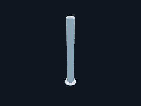
Still column
A short packed column on top of the reboiler. Lets water vapor out and keeps glycol in; a reflux coil at the top condenses glycol back down.
Safety. The vent carries steam and some hydrocarbons; keep clear of the outlet.
Standards: 30 CFR 250.851 (pressure vessels and fired vessels), ASME Boiler and Pressure Vessel Code Section VIII
Show it in 3D: Fixed platform × 1Deepwater TLP × 1
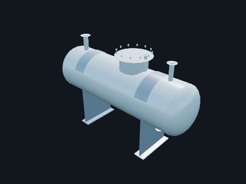
Test separator
A smaller separator that takes one well at a time. Measures that well’s oil, gas and water rates for the periodic well test, then sends the fluids on to the production stream.
Standards: 30 CFR 250.851 (pressure vessels and fired vessels), ASME Boiler and Pressure Vessel Code Section VIII, API 510 (pressure vessel inspection), API RP 14C (surface safety systems; 7th ed. 2001, reaffirmed 2007, per 30 CFR 250.198), API RP 14J (design and hazards analysis; 2nd ed. 2001, reaffirmed 2013, per 30 CFR 250.198)
Show it in 3D: Fixed platform × 1Deepwater TLP × 1
Rotating equipment
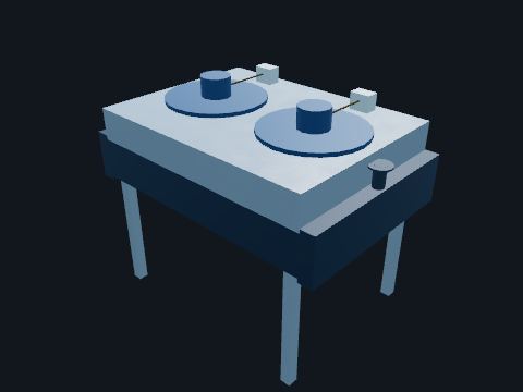
Air-cooled heat exchanger
A finned tube bundle with large fans (a fin-fan). Cools gas or water with air instead of sea water.
Safety. Fans start without warning on temperature control: lock them out before reaching into the plenum.
Standards: API Std 661 (air-cooled heat exchangers)
Show it in 3D: Fixed platform × 1
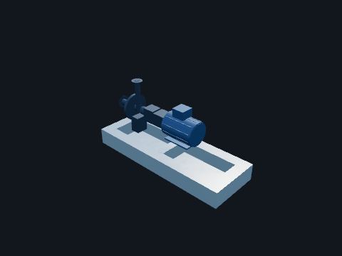
Charge pump
A centrifugal pump on the LACT skid. Keeps the meter and the export pumps flooded with oil at a steady pressure.
Standards: API RP 14C (safety devices on pumps and compressors), API Std 610 (centrifugal pumps)
Show it in 3D: Fixed platform × 2Deepwater TLP × 2
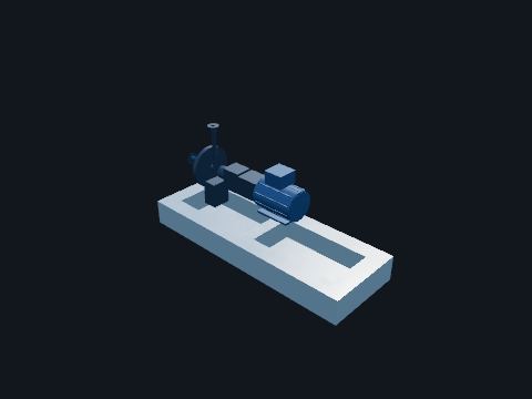
Glycol pump
A small pump on the regeneration skid. Lifts lean glycol up to the top of the contactor at contactor pressure.
Standards: API RP 14C (safety devices on pumps and compressors)
Show it in 3D: Fixed platform × 2Deepwater TLP × 2
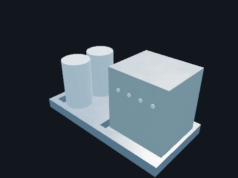
Instrument air package
Air compressors, a dryer and receivers on a skid. Supplies clean, dry air for valve actuators and the pneumatic shutdown loops. Losing air pressure fails the shutdown valves closed.
Safety. Compressed air can blow particles into eyes or skin; never point an air hose at a person.
Standards: API RP 14C
Show it in 3D: Fixed platform × 1Deepwater TLP × 1
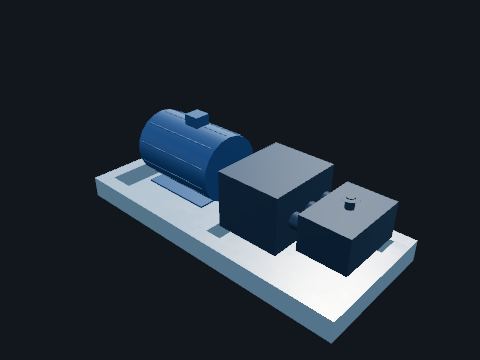
Oil export pump
A large pump that drives oil into the export pipeline. Raises the oil from about atmospheric pressure to the pipeline’s operating pressure.
Safety. High discharge pressure: a closed discharge valve against a running positive-displacement pump will burst something unless the relief valve lifts.
Standards: API RP 14C (safety devices on pumps and compressors), API Std 674 (positive displacement pumps, reciprocating)
Show it in 3D: Fixed platform × 2Deepwater TLP × 3
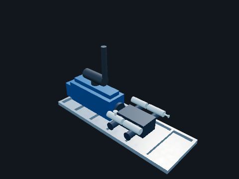
Reciprocating compressor package
A reciprocating compressor on a skid with its driver (a gas engine or an electric motor): frame, cylinders with pulsation bottles, coolers and scrubbers. Raises the pressure of low-pressure flash gas so it can be dehydrated and sold instead of flared.
| Rule | 30 CFR 250.858: scrubber PSH, PSL, PSV, LSH and LSL; a TSH on each cylinder discharge; a blowdown valve on compressors of 1,000 hp or more |
| Testing | 30 CFR 250.880(c)(3)(v): compressor TSHs that can be tested nondestructively, every 6 months |
Safety. Rotating and reciprocating parts behind guards, hot surfaces and high noise: hearing protection is required at the package.
Standards: API RP 14C (safety devices on pumps and compressors), 30 CFR 250.858 (gas compressors), API Std 618 (reciprocating compressors)
Show it in 3D: Fixed platform × 1Deepwater TLP × 1
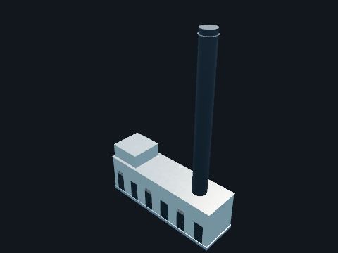
Turbine-driven compressor
A centrifugal gas compressor and the gas turbine that drives it, in an acoustic enclosure with an air inlet filter house and an exhaust stack. Raises dry gas to the export pipeline pressure in one or more casings. The turbine burns fuel gas from the platform.
| Rule | 30 CFR 250.858(a): suction scrubber PSH, PSL, PSV, LSH and LSL; a TSH on each cylinder or case discharge; a blowdown valve on compressors of 1,000 hp or more |
| Rule | 30 CFR 250.856(a): engine exhausts insulated and guarded per API RP 14C (named only) |
Safety. High-speed rotating machinery, hot exhaust and high noise: never enter the enclosure with the fire suppression armed.
Standards: API RP 14C (safety devices on pumps and compressors), 30 CFR 250.858 (gas compressors), API Std 616 (gas turbines), API Std 617 (centrifugal compressors; named only), 30 CFR 250.856 (engines)
Show it in 3D: Deepwater TLP × 2
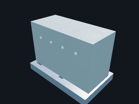
Water maker
A reverse osmosis unit. Makes drinking and washing water from sea water.
Show it in 3D: Fixed platform × 1Deepwater TLP × 1
Piping & valves
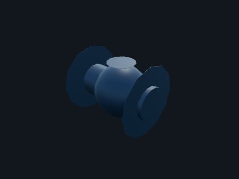
Check valve
A valve that lets flow go only one way. Stops flow backing up from a header into a shut-in well or a pump.
| Testing | 30 CFR 250.880(c)(2)(v): flowline FSVs (flow safety valves, a kind of check valve) monthly, not to exceed 6 weeks |
Standards: API Spec 6D, 30 CFR 250.880(c)(2)(v) (FSV testing)
Show it in 3D: Fixed platform × 9Deepwater TLP × 12
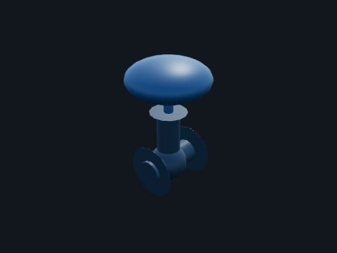
Control valve
A globe valve with a diaphragm actuator and a positioner. Throttles flow to hold a level, pressure or flow at its set point.
Standards: ISA-75 series (control valves)
Show it in 3D: Fixed platform × 3Deepwater TLP × 1

Flowline
The pipe from a well’s choke to the manifold. Carries the well stream at close to the well’s flowing pressure. It must hold the well’s full shut-in pressure in case the choke or a downstream valve closes.
| Rule | 30 CFR 250.852: flowlines have both PSH and PSL sensors, and a working pressure at least the maximum shut-in pressure of the well |
Standards: 30 CFR 250.841(b) (process piping), API RP 14E (offshore production piping; 5th ed. 1991, reaffirmed 2013, per 30 CFR 250.198), API 570 (piping inspection), ASME B31.3 (process piping), 30 CFR 250.852 (flowlines and headers)
Show it in 3D: Fixed platform × 18Deepwater TLP × 24
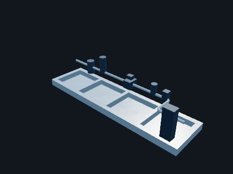
LACT unit
Lease automatic custody transfer skid: charge pumps, strainer, air eliminator, BS&W probe, divert valve, sampler and meter. Meters and samples the oil sold into the pipeline and diverts oil that has too much water back for treating.
| Basis | A manufacturer’s standard 4 in LACT skid is 22 ft 11 in x 6 ft x 7 ft 11-7/8 in, 7,675 lb |
Standards: API MPMS Chapter 6.1 (LACT systems; 2nd ed. 1991 with Addendum 1, 2020, per 30 CFR 250.198), API MPMS Chapter 5 (metering)
Show it in 3D: Fixed platform × 1Deepwater TLP × 1
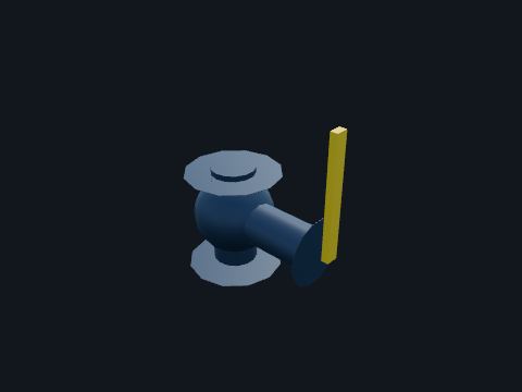
Manual valve
A ball or gate valve worked by hand. Lines flows up and isolates equipment for maintenance.
Safety. A closed valve is not an isolation until it is locked, tagged, and the pipe beyond it has been bled down and checked.
Standards: API Spec 6D
Show it in 3D: Fixed platform × 18Deepwater TLP × 24
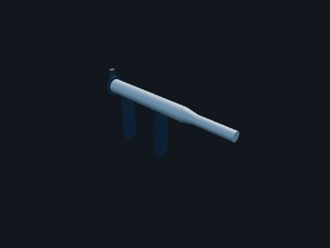
Pig launcher
A larger barrel at the top of a pipeline riser with a quick-opening closure. Sends pigs (scrapers and inspection tools) into the pipeline to clean it and check its wall.
Safety. The closure holds pipeline pressure. It has an interlock and a bleed: confirm zero pressure and open the bleed before opening the door.
Standards: 30 CFR 250.841(b) (process piping), API RP 14E (offshore production piping; 5th ed. 1991, reaffirmed 2013, per 30 CFR 250.198), ASME Section VIII (closures)
Show it in 3D: Fixed platform × 2Deepwater TLP × 2
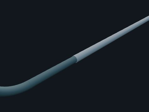
Pipeline
The pipeline that runs along the seabed from the riser to shore or to another platform. Carries the platform’s oil or gas away. Pipelines over 8-5/8 in in water shallower than 200 ft must be buried, so this one in 300 ft of water lies on the seabed.
| Rule | 30 CFR 250.1003: burial in less than 200 ft of water, 18 in separation at crossings, hydrotest at 1.25 times MAOP for 8 hours |
Standards: 30 CFR 250 Subpart J (pipelines and pipeline rights-of-way), 30 CFR 250.1003 (installation, testing and repair), API RP 1111 (offshore hydrocarbon pipelines), 49 CFR 192 / 195 (beyond the platform, where they apply)
Show it in 3D: Fixed platform × 2

Pipeline riser
The steel pipe that brings a pipeline up from the seabed to the deck, clamped to a jacket leg. Connects the platform’s export pumps or compressors to the subsea pipeline. Risers have their own shutdown valve at the top so a fire on the platform can be cut off from the pipeline’s inventory.
| Rule | 30 CFR 250.1004(b)(3): departing pipelines receiving production from production facilities are protected by high- and low-pressure sensors |
| Not a BSDV | BSEE’s boarding shutdown valve rules (30 CFR 250.835, 250.838) cover pipelines that bring production from subsea wells on board; these risers export from the platform |
Safety. A riser holds the whole pipeline’s pressure. A leak at the splash zone is the worst case: report any coating damage or bubbles.
Standards: 30 CFR 250 Subpart J (pipelines and pipeline rights-of-way), 30 CFR 250.1003 (installation, testing and repair), API RP 1111 (offshore hydrocarbon pipelines), 49 CFR 192 / 195 (beyond the platform, where they apply), 30 CFR 250.1004(b)(3) (departing pipelines: high- and low-pressure sensors)
Show it in 3D: Fixed platform × 2Deepwater TLP × 2
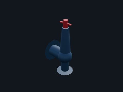
Pressure safety valve (PSV)
A spring-loaded relief valve on top of a vessel or line. Opens if the pressure reaches its set point and sends the excess to the flare. It is the last protection when the controls and the PSH have both failed.
| Rule | 30 CFR 250.851(a): set no higher than the vessel’s maximum allowable working pressure |
| Testing | 30 CFR 250.880(c)(2)(i): annually, not to exceed 12 calendar months |
Safety. Never block in a PSV. A PSV lifting is loud and can blow liquid out of the flare: report every lift.
Standards: 30 CFR 250.851(a) (set no higher than MAWP), 30 CFR 250.880(c)(2)(i) (annual testing), API Std 520 (sizing and installation), API Std 526 (flanged steel relief valves), API Std 527 (seat tightness)
Show it in 3D: Fixed platform × 3Deepwater TLP × 4
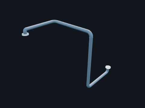
Process piping
Steel pipe carrying oil, gas or water between equipment. Pipe size, material and wall thickness are set for the pressure, the temperature, the fluid and how fast it erodes or corrodes the pipe.
| Rule | 30 CFR 250.841(b): process piping designed, installed, maintained and inspected per API RP 14E and API 570 (named only) |
Safety. Treat every pipe as live until you have seen it isolated and bled. Small-bore connections break first: never use them as steps or handholds.
Standards: 30 CFR 250.841(b) (process piping), API RP 14E (offshore production piping; 5th ed. 1991, reaffirmed 2013, per 30 CFR 250.198), API 570 (piping inspection), ASME B31.3 (process piping)
Show it in 3D: Fixed platform × 57Deepwater TLP × 63

Relief and flare piping
Headers that collect the discharge of relief valves and blowdown valves. Carry relieved gas to the knockout drum and the flare. They slope toward the drum so liquid cannot collect.
Standards: 30 CFR 250.841(b) (process piping), API RP 14E (offshore production piping; 5th ed. 1991, reaffirmed 2013, per 30 CFR 250.198), API 570 (piping inspection), ASME B31.3 (process piping), API Std 521
Show it in 3D: Fixed platform × 5Deepwater TLP × 5
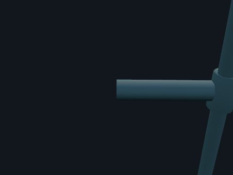
Riser clamp
A bolted split clamp with a rubber liner that holds the riser to the jacket. Keeps the riser in line and carries its weight and wave loads into the jacket without rubbing through the coating.
Standards: 30 CFR 250 Subpart I (platforms and structures), API RP 2A-WSD (fixed offshore platforms; 22nd ed. 2014, reaffirmed 2020, per 30 CFR 250.198)
Show it in 3D: Fixed platform × 2Deepwater TLP × 2
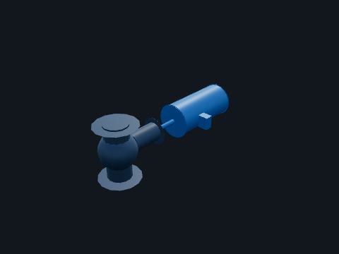
Shutdown valve (SDV)
An actuated valve that fails closed, with a spring-return actuator and a solenoid that vents it. Closes on a process shutdown or ESD to cut off a vessel, a pipeline or a compressor from its sources. The shutdown valve where a pipeline carrying production from subsea wells boards a platform is a boarding shutdown valve (BSDV), with rules of its own.
| Testing | 30 CFR 250.880(c)(2)(ii): automatic inlet SDVs monthly, not to exceed 6 weeks; 30 CFR 250.880(c)(4)(iii): BSDVs monthly, not to exceed 6 weeks |
| BSDV | 30 CFR 250.835(b), 250.838: on a pipeline from subsea wells, the BSDV is fire rated for 30 minutes and closes within 45 seconds after sensor activation. The export riser valves on these platforms are not BSDVs |
Safety. An SDV can close without warning. Never bypass one without the permit, flagging and monitoring 30 CFR 250.869 requires.
Standards: API RP 14C, 30 CFR 250.880(c)(2)(ii), (iii) (SDV testing)
Show it in 3D: Fixed platform × 3Deepwater TLP × 3
Instruments & controls
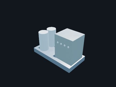
Chemical injection skid
Tanks and small metering pumps. Injects methanol to stop hydrates and corrosion inhibitor to protect the pipe.
Safety. Methanol is toxic and burns with an almost invisible flame.
Standards: API RP 14C
Show it in 3D: Fixed platform × 1Deepwater TLP × 1

Control tubing
Small stainless tubing from the wellhead control panel to the trees. Carries the hydraulic pressure that holds the safety valves open.
Standards: 30 CFR 250.810-250.821 (subsurface and surface safety devices)
Show it in 3D: Fixed platform × 10Deepwater TLP × 9
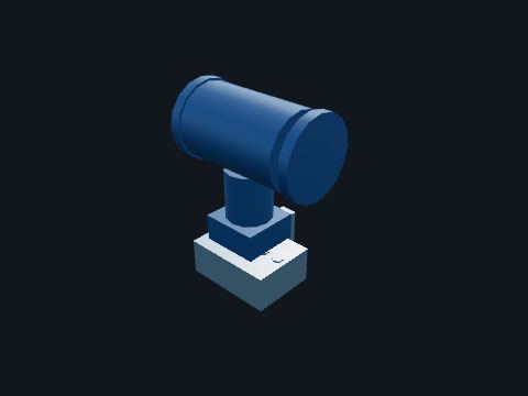
Differential pressure transmitter
A transmitter that measures the difference between two pressures, on a five-valve manifold. With an orifice plate it measures flow; the manifold lets a technician isolate, equalize, zero and vent it.
Safety. Never open the equalizing valve with both block valves open: that connects the two sides of the orifice through the transmitter.
Standards: ISA-5.1 (instrument symbols and identification), API RP 14C, 30 CFR 250.880(c)(3)(ix), (x) (sensor testing), API MPMS Chapter 14.3
Show it in 3D: Fixed platform × 1Deepwater TLP × 1

Heated instrument enclosure
An insulated fiberglass box around a transmitter and its manifold, with a small electric heater and thermostat. Keeps the instrument and the gas in its tubing warm enough that water and hydrates cannot form in the sensing lines.
| Basis | Manufacturer data: 100 W heater with a 50 °F thermostat; rated Class I Division 1 Groups B, C, D, T3 |
| Where used | Shown on the gas meter transmitter as an example. Freezing weather is uncommon on the Gulf of Mexico shelf, so whether a transmitter is heated depends on the service and the operator (Model value) |
Safety. The heater circuit is live inside a classified area: open the box only with the circuit isolated or a hot work permit.
Standards: 30 CFR 250.114 (electrical equipment and area classification), API RP 14F (5th ed. 2008, reaffirmed 2013) / RP 14FZ (2nd ed. 2013), offshore electrical systems, per 30 CFR 250.198, API RP 500 (3rd ed. 2012) / RP 505 (1st ed. 1997, reaffirmed 2013), area classification, per 30 CFR 250.198
Show it in 3D: Fixed platform × 1Deepwater TLP × 1
Impulse tubing
Small stainless tubing from the process taps to a remote instrument. Carries the process pressure to the transmitter. It is sloped so liquid drains back to the line in gas service.
| Basis | Manufacturer installation guidance: 1/2 in OD stainless tubing, wall at least 0.035 in, horizontal runs sloped at least 1 in per ft, transmitter above the taps for gas and below for liquid |
Safety. Tubing holds full line pressure: never loosen a fitting to bleed it.
Standards: ISA-5.1 (instrument symbols and identification), ASTM A269 (stainless tubing)
Show it in 3D: Fixed platform × 1Deepwater TLP × 1
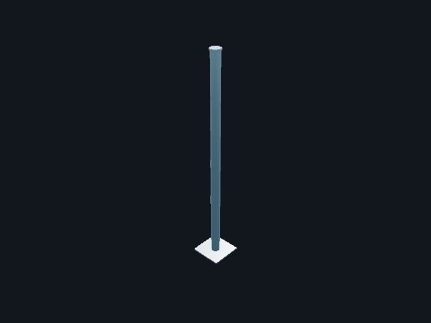
Instrument stand
A 2 in pipe post on a base plate. Holds remote-mounted instruments at a working height and clear of pipe vibration.
Standards: ISA-5.1 (instrument symbols and identification)
Show it in 3D: Fixed platform × 1Deepwater TLP × 1
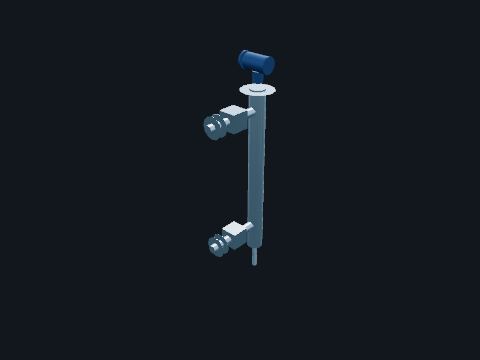
Level transmitter (guided wave radar)
A radar transmitter on top of an external chamber joined to the vessel above and below the liquid. Sends a microwave pulse down a probe; the reflection from the liquid surface, and from the oil-water interface, gives the levels.
| Testing | 30 CFR 250.880(c)(3)(ix): electronic LSH and LSL transmitters tested at least every 3 months, not to exceed 120 days |
Safety. The chamber holds the vessel’s fluid: isolate and drain it before removing the probe.
Standards: ISA-5.1 (instrument symbols and identification), API RP 14C, 30 CFR 250.880(c)(3)(ix), (x) (sensor testing)
Show it in 3D: Fixed platform × 2Deepwater TLP × 1
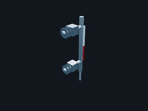
Magnetic level gauge
A chamber with a magnetic float and a column of flags that flip color. Shows the level at the vessel without power.
Standards: ISA-5.1 (instrument symbols and identification)
Show it in 3D: Fixed platform × 2Deepwater TLP × 1

Orifice meter
A pair of orifice flanges holding a thin plate with a precisely bored hole. The pressure difference across the plate gives the gas flow. Used here for custody measurement of the gas sold.
Standards: API MPMS Chapter 14.3 (orifice metering of natural gas), AGA Report No. 3 (named only)
Show it in 3D: Fixed platform × 1Deepwater TLP × 1
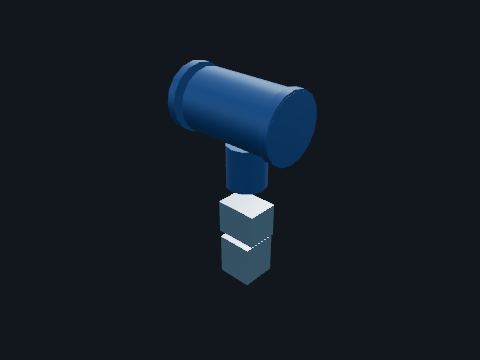
Pressure transmitter
An electronic transmitter on a root valve and manifold. Sends a 4 to 20 mA signal for the pressure to the control and shutdown systems. The PSH and PSL trips are set on its reading.
| Testing | 30 CFR 250.880(c)(3)(ix): electronic PSH and PSL transmitters tested at least every 3 months, not to exceed 120 days |
Standards: ISA-5.1 (instrument symbols and identification), API RP 14C, 30 CFR 250.880(c)(3)(ix), (x) (sensor testing)
Show it in 3D: Fixed platform × 2Deepwater TLP × 1

Process control panel
The PLC and the operator station. Runs the control loops (levels, pressures, flows) and shows the operator what the plant is doing.
Standards: ISA-5.1
Show it in 3D: Fixed platform × 1Deepwater TLP × 1
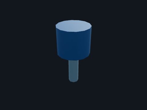
Temperature transmitter
A temperature sensor in a thermowell with a transmitter head. The thermowell keeps the process in; the sensor can be pulled out with the vessel running.
Standards: ISA-5.1 (instrument symbols and identification), API RP 14C, ASME PTC 19.3 TW (thermowells)
Show it in 3D: Fixed platform × 1Deepwater TLP × 1
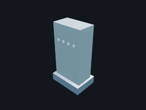
Wellhead control panel
A skid with hydraulic pumps, accumulators and a pneumatic pilot system. Holds every SSV and SCSSV open. Any shutdown signal vents a pilot, the control pressure drops and the valves close: SSVs first, then the SCSSVs.
| SCSSV | 30 CFR 250.814(a): set at least 100 ft below the mudline; 30 CFR 250.821(b): closes within 2 minutes after the SSV |
| Testing | 30 CFR 250.880(c)(1)(i): SCSSVs on dry trees semi-annually, not to exceed 6 months |
Safety. Hydraulic lines at several thousand psi: never loosen a fitting under pressure.
Standards: 30 CFR 250.810-250.821 (subsurface and surface safety devices), API Spec 6A (wellhead and tree equipment; 21st ed. 2018 with errata and addenda, per 30 CFR 250.198), API Std 6AV1 (SSV/USV validation; 3rd ed. 2018, per 30 CFR 250.198), API Std 6AV2 (SSV/USV installation, maintenance and repair), 30 CFR 250.814 (SCSSV setting depth)
Show it in 3D: Fixed platform × 1Deepwater TLP × 1
Safety systems
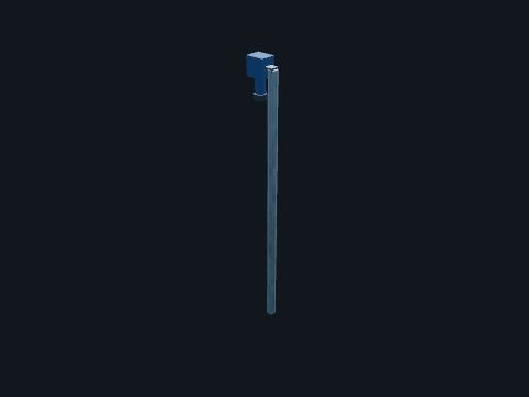
Combustible gas detector
A point detector that measures flammable gas as a percent of its lower explosive limit (LEL). Raises an alarm at the low set point and starts a shutdown at the high set point.
| Rule | 30 CFR 250.862(a): gas sensors in all inadequately ventilated, enclosed classified areas; a gas detection system is not required for quarters that do not contain a gas source. The detectors drawn in open areas and at air intakes here are common practice, not a rule. |
Safety. If a gas alarm sounds, stop hot work, move upwind and go to your muster point.
Standards: 30 CFR 250.862, 30 CFR 250.880(c)(3)(ii), API RP 14C
Show it in 3D: Fixed platform × 6Deepwater TLP × 8

Deluge system
A ring of open spray nozzles over an area, fed through a deluge valve. When the valve opens, every nozzle sprays at once, cooling equipment and steel so a fire cannot spread or weaken the structure.
| Rule | 30 CFR 250.859(a): fixed water spray in enclosed well-bay areas where hydrocarbon vapors may accumulate |
Safety. A deluge can start without warning: water is not a hazard, but the noise and spray can startle you near an edge.
Standards: 30 CFR 250.859 (firefighting systems), API RP 14G (fire prevention and control; 4th ed. 2007, reaffirmed 2013, per 30 CFR 250.198), NFPA 15 (water spray fixed systems; named only)
Show it in 3D: Fixed platform × 1Deepwater TLP × 1
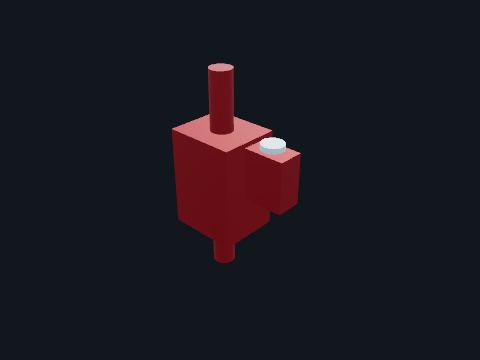
Deluge valve
A large valve on the fire main that holds water back from an open-nozzle system. Opens on a fire signal or by its manual release and floods the deluge ring.
Standards: 30 CFR 250.859 (firefighting systems), API RP 14G (fire prevention and control; 4th ed. 2007, reaffirmed 2013, per 30 CFR 250.198), NFPA 15
Show it in 3D: Fixed platform × 1Deepwater TLP × 1

ESD station
A red pull station that shuts in the whole platform. Vents the ESD loop: every SSV and SDV closes, the riser shutdown valves included, the SCSSVs follow, the compressor and pumps stop and the flare takes the blowdown.
| Rule | 30 CFR 250.855: ESD per API RP 14C (named only; 30 CFR 250.198 incorporates the 7th edition, 2001, reaffirmed 2007) Appendix C; stations uniquely identified; electronic stations de-energize to trip or supervised |
| Testing | 30 CFR 250.880(c)(3)(iii): pneumatic ESD monthly; electronic ESD every 3 months, not to exceed 120 days |
Safety. Pull it when you see a fire, a leak you cannot stop, or anything that will get worse. You will not be blamed for a good-faith ESD.
Standards: 30 CFR 250.855 (ESD system), 30 CFR 250.880(c)(3)(iii) (ESD testing), API RP 14C Appendix C
Show it in 3D: Fixed platform × 9Deepwater TLP × 8

Eyewash station
An eyewash near the batteries. Rinses electrolyte from the eyes.
| Rule | OSHA 29 CFR 1910.151(c): eyewash where corrosive materials can splash (general industry rule, shown as good practice) |
Standards: 33 CFR 142.48 (eyewash), ANSI Z358.1 (named only)
Show it in 3D: Fixed platform × 1Deepwater TLP × 1

Fire and gas panel
Reads the gas, flame, heat and smoke detectors and the manual alarm stations. Raises alarms and starts shutdowns, fire pumps and suppression on confirmed fire or gas.
| Testing | 30 CFR 250.880(c)(3)(ii): fire and gas detection tested and recalibrated every 3 months, not to exceed 120 days |
Standards: 30 CFR 250.862 (fire and gas detection), API RP 14C, NFPA 72 (named only)
Show it in 3D: Fixed platform × 1Deepwater TLP × 1

Fire hose reel
A reel of fire hose with a nozzle, on the fire water main. Lets one person put water on a fire quickly.
Safety. Only fight a fire you can put out with what is in your hands, with your exit behind you. Otherwise raise the alarm and muster.
Standards: 30 CFR 250.859 (firefighting systems), API RP 14G (fire prevention and control; 4th ed. 2007, reaffirmed 2013, per 30 CFR 250.198)
Show it in 3D: Fixed platform × 3Deepwater TLP × 3
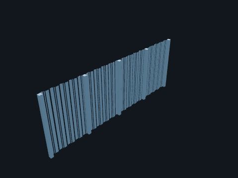
Fire wall
A wall of steel panels rated to keep a hydrocarbon fire out for a set time. Separates the process from the quarters, the electrical building and the utilities, so a fire in one area does not spread to the next.
Safety. Doors in a fire wall are self-closing: never wedge them open.
Standards: API RP 2FB (fire and blast; named only), 33 CFR 143 Subpart (structural fire protection, named)
Show it in 3D: Fixed platform × 2Deepwater TLP × 1

Fire water main
Red pipe carrying sea water from the fire pumps to hose reels, monitors and spray systems. Kept full and under pressure so water reaches a fire within seconds of opening a hose.
| Rule | 30 CFR 250.859(a): a firewater system of rigid pipe with fire hose stations and/or fixed monitors; fixed water spray in enclosed well bays |
Standards: 30 CFR 250.859 (firefighting systems), API RP 14G (fire prevention and control; 4th ed. 2007, reaffirmed 2013, per 30 CFR 250.198)
Show it in 3D: Fixed platform × 4Deepwater TLP × 2
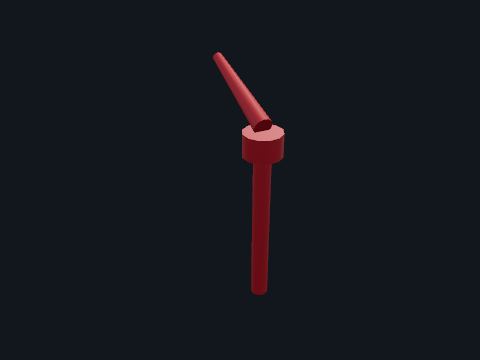
Fire water monitor
A large aimable nozzle on a fire water riser. Throws a heavy stream of water or foam a long way, for cooling or for fires that hose reels cannot reach.
Standards: 30 CFR 250.859 (firefighting systems), API RP 14G (fire prevention and control; 4th ed. 2007, reaffirmed 2013, per 30 CFR 250.198)
Show it in 3D: Fixed platform × 1Deepwater TLP × 2
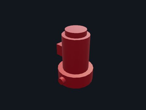
Fire water pump
A vertical pump that lifts sea water through a caisson into the fire main. Supplies the hose reels, monitors and spray systems. Two pumps with independent drivers mean one failure does not leave the platform dry.
| Rule | 30 CFR 250.859(a)(2): fuel or power for fire pump drivers for at least 30 minutes; an automatic transfer switch to emergency power for electric fire pumps |
| Testing | 30 CFR 250.880(c)(3)(i): inspected and operated per API RP 14G section 7.2 (named only) |
Safety. The diesel pump can start by itself at any time.
Standards: 30 CFR 250.859 (firefighting systems), API RP 14G (fire prevention and control; 4th ed. 2007, reaffirmed 2013, per 30 CFR 250.198), 30 CFR 250.880(c)(3)(i) (fire pump inspection per API RP 14G section 7.2), NFPA 20 (stationary fire pumps; named only), 46 CFR 108.415, 108.417 (floating units: at least two independently driven fire pumps)
Show it in 3D: Fixed platform × 2Deepwater TLP × 2
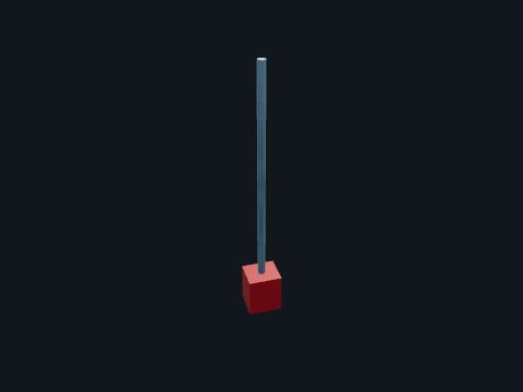
Flame detector
An optical detector that sees the infrared signature of a hydrocarbon flame. Detects a fire within a second or two and starts alarms and shutdowns.
| Rule | 30 CFR 250.862(a): fire sensors (flame, heat or smoke) in all enclosed classified areas |
Standards: 30 CFR 250.862, 30 CFR 250.880(c)(3)(ii)
Show it in 3D: Fixed platform × 3Deepwater TLP × 4
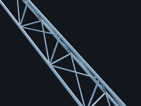
Flare boom
A long lattice boom angled up from the end of the platform. Holds the flare tip far enough out that the heat of a full blowdown stays off the decks.
| Basis | Booms of about 50 to 100 ft at about 30° are typical (published patent description of Gulf of Mexico flare booms) |
Standards: API Std 521, API Std 537 (flare details; named only)
Show it in 3D: Fixed platform × 1Deepwater TLP × 1
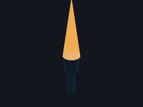
Flare tip
The burner at the end of the boom with a wind shield and pilot burners. Burns the gas sent to the flare; the pilots keep it ready to light.
Safety. A flare that goes out while gas is flowing releases unburned gas: report it.
Standards: API Std 521, API Std 537 (named only)
Show it in 3D: Fixed platform × 1Deepwater TLP × 1

Fusible plug loop (TSE)
A loop of small pneumatic tubing with plugs that melt in a fire. A melted plug vents the loop and shuts in the wells. Simple, needs no power, and covers a whole area.
| Rule | 30 CFR 250.818(c): surface-controlled SSSVs close in response to the fire loop or other fire detection devices |
Standards: API RP 14C, 30 CFR 250.818(c) (SCSSV response to the fire loop)
Show it in 3D: Fixed platform × 1Deepwater TLP × 1

Guard rail
Steel pipe rails around every open deck edge and opening, with a toe board at the bottom. Stops people and dropped tools going over the edge. On U.S. OCS fixed platforms the rail height and toe board come from Coast Guard rules.
| Rule | 33 CFR 143.110(a): guard rails at least 42 in high; with a toe board, one intermediate rail about halfway between the toe board and the top rail |
Safety. Never sit on, climb or lean out over a rail. A removed rail section is an open edge: barricade it and use fall protection.
Standards: 33 CFR 143.110 (guards and rails)
Show it in 3D: Fixed platform × 36Deepwater TLP × 26
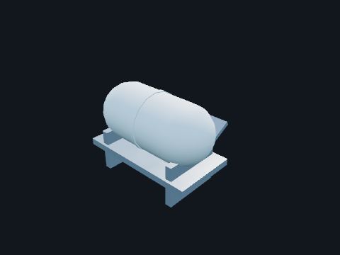
Inflatable liferaft
A raft packed in a canister on a cradle, with a hydrostatic release. Thrown over or released, it inflates in the water. The release frees it automatically if the platform goes down.
| Rule | 33 CFR 144.01-15(d): inflatable liferafts approved under series 160.151 |
Standards: 33 CFR Part 144 (lifesaving appliances), 33 CFR Part 146 (operations: station bill, alarms, drills), 33 CFR 144.01-15(d) (approval series 160.151), 46 CFR 108.525(a)(2) (floating units: float-free liferafts for everyone on board)
Show it in 3D: Fixed platform × 2Deepwater TLP × 6

Ladder to the water
A fixed steel ladder from the boat landing down into the water. The last part of the escape route: from the lowest working level down to the water surface where a rescue boat or life float can pick people up.
| Rule | 33 CFR 143.101(c): each primary means of escape reaches the water surface |
Safety. Only go into the water when ordered to abandon and there is no other way off.
Standards: 33 CFR 143.101 (means of escape), 33 CFR 143.110 (guards and rails), 33 CFR 142.42 (safety belts and lifelines; fall hazard of 10 ft or more)
Show it in 3D: Fixed platform × 2
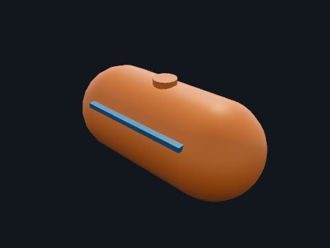
Lifeboat (survival craft)
A totally enclosed motor-propelled survival craft in a davit. When the platform must be abandoned, people board inside, strap in and are lowered to the sea; the boat motors away from the platform.
| Rule | 33 CFR 144.01-15: approved lifeboats or liferafts may be used in place of the required life floats; 33 CFR 144.01-1: capacity for all persons on board |
Safety. Board in the order the coxswain gives and strap in before the boat is lowered.
Standards: 33 CFR Part 144 (lifesaving appliances), 33 CFR Part 146 (operations: station bill, alarms, drills), 46 CFR 160.135 (lifeboats; approval series, named), 46 CFR 108.520, 108.525(a)(1) (floating units: fire-protected lifeboats in two widely separated locations, each side holding everyone on board)
Show it in 3D: Fixed platform × 4Deepwater TLP × 10
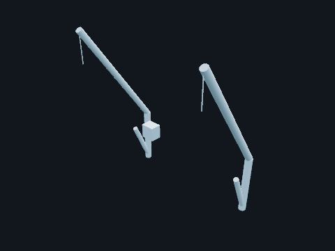
Lifeboat davit
The arms and winch that hold a lifeboat and lower it. Gravity lowers the boat when the brake is lifted; nothing else is needed.
Safety. Only trained crew operate the davit; drills follow the platform’s station bill.
Standards: 33 CFR Part 144 (lifesaving appliances), 33 CFR Part 146 (operations: station bill, alarms, drills), 46 CFR 160.132 (davits; approval series, named)
Show it in 3D: Fixed platform × 4Deepwater TLP × 10
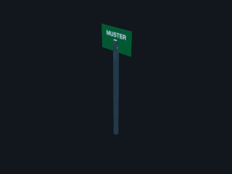
Muster station
A marked place where people gather and are counted when the alarm sounds. The person in charge counts everyone against the list before deciding the next step.
| Rule | 33 CFR 146.110: the alarm signals and the station bill; drills at least monthly (see the Safety guide) |
Safety. Go straight to your muster station on the alarm; do not stop to collect belongings.
Standards: 33 CFR 146.105 (station bill), 33 CFR 146.110 (alarms), 33 CFR 146.125 (drills)
Show it in 3D: Fixed platform × 2Deepwater TLP × 2
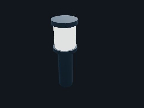
Obstruction light
White flashing lights on each corner of the platform. Mark the platform for ships at night. U.S. OCS structures are private aids to navigation under Coast Guard rules, which set the color, flash rate, range and height.
| Rule | 33 CFR Part 67 (67.05, 67.20) |
Safety. Report a light out to the control room: the Coast Guard requires prompt repair.
Standards: 33 CFR Part 67 (aids to navigation on artificial islands and fixed structures), 33 CFR 143.15
Show it in 3D: Fixed platform × 1Deepwater TLP × 1
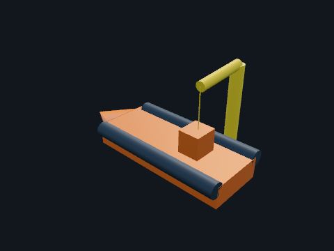
Rescue boat
A fast open boat in its own davit, kept ready for a person in the water. Picks up anyone who falls overboard and marshals the liferafts after an abandonment.
| Rule | 46 CFR 108.560: each unit carries at least one rescue boat |
Safety. Only the trained rescue boat crew launch it, in survival suits and helmets.
Standards: 46 CFR 108.560 (at least one rescue boat), 33 CFR 143.120 (floating OCS facilities: Coast Guard vessel rules in 46 CFR apply)
Show it in 3D: Deepwater TLP × 1
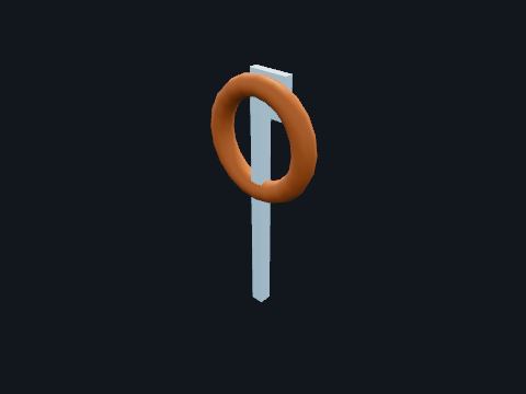
Ring life buoy
An orange ring buoy with a light, on each side of the platform. Thrown to a person in the water.
| Rule | 33 CFR 144.01-25: ring life buoys on manned platforms |
Safety. Throw it, do not jump in after someone.
Standards: 33 CFR 144.01-25 (ring life buoys)
Show it in 3D: Fixed platform × 4Deepwater TLP × 8
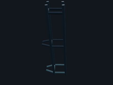
Riser guard
A frame of steel tubes around the riser where it passes the waterline. Keeps boats and swinging loads from hitting the riser at the splash zone, where a hole would release the pipeline’s inventory.
| Basis | Riser guards below the cellar deck are reported on Gulf platforms (BSEE incident report, 2015) |
Standards: 30 CFR 250 Subpart I (platforms and structures), API RP 2A-WSD (fixed offshore platforms; 22nd ed. 2014, reaffirmed 2020, per 30 CFR 250.198)
Show it in 3D: Fixed platform × 2

Safety shutdown panel
The logic that turns sensor trips and ESD pushes into valve closures and equipment trips. Carries out the shutdown functions the SAFE chart lists for every sensor.
| Rule | 30 CFR 250.842(a)(1): a SAFE chart and safety analysis flow diagram per API RP 14C (named only; 30 CFR 250.198 incorporates the 7th edition, 2001, reaffirmed 2007) |
Standards: 30 CFR 250.855 (ESD system), API RP 14C, ISA-84 / IEC 61511 (safety instrumented systems)
Show it in 3D: Fixed platform × 1Deepwater TLP × 1

Sound signal
An electric horn that sounds in fog. Warns ships when visibility is poor. It is mounted where nothing blocks its sound in any direction.
| Rule | 33 CFR Part 67 (67.10, 67.20-10) |
Safety. The horn is loud: wear hearing protection when working near it.
Standards: 33 CFR Part 67, 33 CFR 143.15
Show it in 3D: Fixed platform × 1Deepwater TLP × 1
Electrical power

AC and DC distribution panels
Panelboards fed from the UPS. Distribute uninterrupted power to the panels, radios and field devices.
Standards: 30 CFR 250.114 (electrical equipment and area classification), API RP 14F (5th ed. 2008, reaffirmed 2013) / RP 14FZ (2nd ed. 2013), offshore electrical systems, per 30 CFR 250.198
Show it in 3D: Fixed platform × 1Deepwater TLP × 1
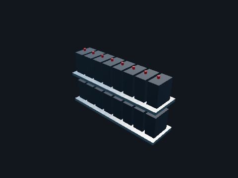
Battery bank
Racks of sealed lead-acid batteries. Carry the UPS loads when every generator is down.
Safety. Batteries can deliver very high short-circuit current and give off hydrogen when charging. Insulated tools only.
Standards: IEEE 485 (lead-acid battery sizing), IEEE 1188 (VRLA maintenance and testing), NFPA 70 Article 480
Show it in 3D: Fixed platform × 1Deepwater TLP × 1
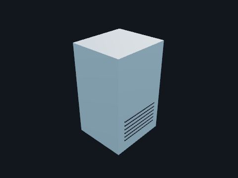
Dry-type transformer
A transformer with air-cooled windings in a ventilated enclosure. Steps 4,160 V down to 480 V for the motor control centers.
| Basis | Manufacturer data for a 1,500 kVA, 4,160-480 V unit: 90 x 90 x 50 in, 7,900 lb (NEMA 1 indoor enclosure) |
Standards: 30 CFR 250.114 (electrical equipment and area classification), API RP 14F (5th ed. 2008, reaffirmed 2013) / RP 14FZ (2nd ed. 2013), offshore electrical systems, per 30 CFR 250.198, IEEE C57.12.01 (dry-type transformers)
Show it in 3D: Fixed platform × 2Deepwater TLP × 4
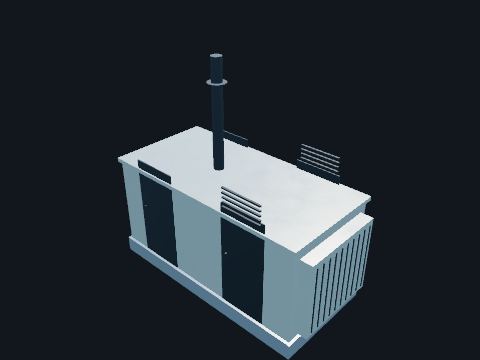
Emergency diesel generator
A diesel engine generator with its own radiator, fuel tank and batteries. Starts by itself when the main power fails and feeds the emergency loads: emergency lighting, the UPS chargers, fire pump controls, navigation aids and radios.
| Rule | 30 CFR 250.856: diesel exhausts have spark arresters; emergency generator engines are exempt from the air-intake shutdown device |
Standards: 30 CFR 250.114 (electrical equipment and area classification), API RP 14F (5th ed. 2008, reaffirmed 2013) / RP 14FZ (2nd ed. 2013), offshore electrical systems, per 30 CFR 250.198, 30 CFR 250.856 (engines; emergency generator exemption)
Show it in 3D: Fixed platform × 1Deepwater TLP × 1
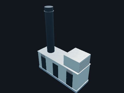
Gas turbine generator
A gas turbine and generator in an acoustic enclosure, with its air inlet filter house and exhaust stack. Makes the platform’s electric power from fuel gas. One more unit is installed than the load needs, so a set can stand by or be shut down for maintenance.
| Rule | 30 CFR 250.856(a): engine exhausts insulated and guarded per API RP 14C (named only) |
Safety. The enclosure has its own gas and fire detection and a suppression system that floods it: never enter while the suppression system is armed.
Standards: 30 CFR 250.114 (electrical equipment and area classification), API RP 14F (5th ed. 2008, reaffirmed 2013) / RP 14FZ (2nd ed. 2013), offshore electrical systems, per 30 CFR 250.198, API Std 616 (gas turbines), 30 CFR 250.856 (engines)
Show it in 3D: Fixed platform × 2Deepwater TLP × 3
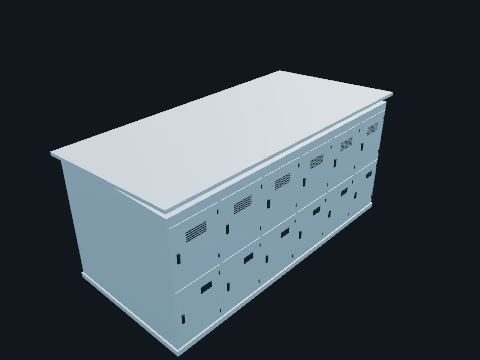
Medium-voltage switchgear
A line-up of metal-clad cubicles with draw-out vacuum circuit breakers. The main 4,160 V bus: the generators feed it and it feeds the large motors and the transformers.
| Basis | Manufacturer data: 5 kV metal-clad sections 36 in wide and 95 in high |
Safety. Arc-flash hazard: work on energized gear only with the arc-flash label’s PPE and a permit. Rack breakers remotely where possible.
Standards: 30 CFR 250.114 (electrical equipment and area classification), API RP 14F (5th ed. 2008, reaffirmed 2013) / RP 14FZ (2nd ed. 2013), offshore electrical systems, per 30 CFR 250.198, API RP 500 (3rd ed. 2012) / RP 505 (1st ed. 1997, reaffirmed 2013), area classification, per 30 CFR 250.198, NFPA 70 Articles 500-505 (hazardous locations), NFPA 70E (electrical safety in the workplace), IEEE C37.20.2 (metal-clad switchgear)
Show it in 3D: Fixed platform × 1Deepwater TLP × 2
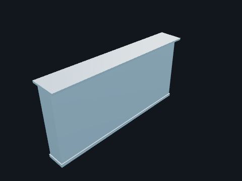
Motor control center (MCC)
A line-up of 480 V sections with plug-in buckets: starters and feeder breakers. Feeds the smaller motors, the heaters and the lighting transformers.
| Basis | Manufacturer data: sections 90 in high and 20 in wide, 16 or 21 in deep, with buckets in 6 in spaces |
Safety. Lock out at the bucket and test for absence of voltage at the motor before work.
Standards: 30 CFR 250.114 (electrical equipment and area classification), API RP 14F (5th ed. 2008, reaffirmed 2013) / RP 14FZ (2nd ed. 2013), offshore electrical systems, per 30 CFR 250.198, API RP 500 (3rd ed. 2012) / RP 505 (1st ed. 1997, reaffirmed 2013), area classification, per 30 CFR 250.198, NFPA 70 Articles 500-505 (hazardous locations), NFPA 70E (electrical safety in the workplace), UL 845 (motor control centers)
Show it in 3D: Fixed platform × 1Deepwater TLP × 1

UPS rectifier and charger
A cabinet that charges the batteries and feeds the inverter. Keeps the safety and control panels powered without a break if main power fails.
Standards: IEEE 1188
Show it in 3D: Fixed platform × 1Deepwater TLP × 1
Cable, tray & conduit
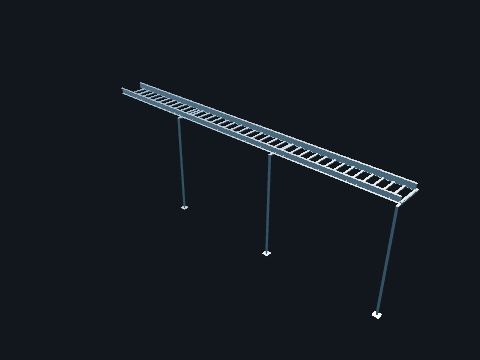
Cable tray
Aluminum ladder tray: two side rails joined by rungs. Carries and supports the cables between the electrical building and the equipment, with power and instrument cables in separate trays.
| Basis | Manufacturer catalog data: 6063-T6 aluminum, 6 in side rail, 5 in loading depth, 20 ft sections; support span no longer than the section length, one splice per span |
| Lesson | BSEE Safety Alert 339 (2018): a gas sensing line run in a cable tray led to a fire. Keep tubing and piping out of trays. |
Safety. Trays are not walkways or ladders. Never run tubing or hoses in them.
Standards: 30 CFR 250.114 (electrical equipment and area classification), API RP 14F (5th ed. 2008, reaffirmed 2013) / RP 14FZ (2nd ed. 2013), offshore electrical systems, per 30 CFR 250.198, NEMA VE 1 (metal cable tray systems), NEMA VE 2 (installation guidelines), BSEE Safety Alert 339 (2018)
Show it in 3D: Fixed platform × 9Deepwater TLP × 8
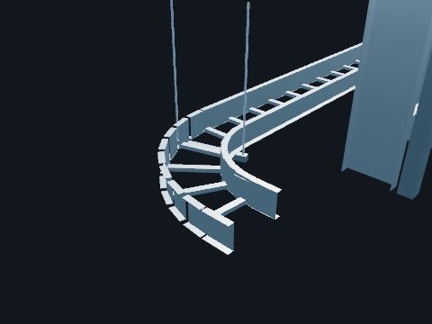
Cable tray fitting
A factory-made curved or branching piece of ladder tray: a horizontal bend, a vertical inside or outside bend, or a tee. Lets the tray change direction or branch without bending the cables tighter than they can take. Each fitting is bolted to the straight sections with splice plates on both side rails.
| Basis | Manufacturer catalog data: 90° fittings at 12, 24 or 36 in radius; 24 in here. A cable distributor’s engineering guide gives the smallest permanent bend for shielded or armored multi-conductor cable as 7 times its outside diameter, so the 2.3 in cables here need at least about 16 in |
Safety. Do not cut and field-bend straight tray to make a turn: use the fitting.
Standards: 30 CFR 250.114 (electrical equipment and area classification), API RP 14F (5th ed. 2008, reaffirmed 2013) / RP 14FZ (2nd ed. 2013), offshore electrical systems, per 30 CFR 250.198, NEMA VE 1 (metal cable tray systems), NEMA VE 2 (installation guidelines), BSEE Safety Alert 339 (2018)
Show it in 3D: Fixed platform × 16Deepwater TLP × 13

Conduit and tubing supports
Short strut stands with a pipe clamp, or threaded rods with a clamp, along the field conduit and tubing runs. Hold the conduit and tubing between the device and its box so the runs do not sag, vibrate or get used as a step.
Safety. Never stand on or hang anything from a conduit run.
Standards: NFPA 70 Article 344 (rigid metal conduit, including its support; named only), API RP 14F (electrical systems for fixed offshore platforms; named only)
Show it in 3D: Fixed platform × 29Deepwater TLP × 32
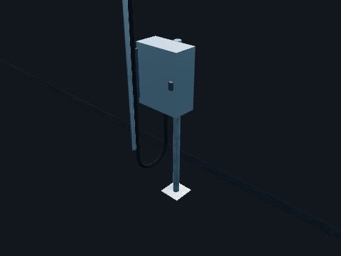
Field junction box
A stainless steel box on a pipe stand with rows of terminals inside and cable glands in its bottom plate. Where a multi-pair cable from the safety and control panels splits out into single-pair cables for the field instruments. The cables come up into the bottom so rain cannot run in along them.
| Basis | Generic offshore practice; size and terminal count: Model value |
| Hazardous area | Increased safety (Ex e) terminals, a protection method for Zone 1 recognized in NFPA 70 Article 505 (named only) |
Safety. Opening a box in a classified area while its circuits are live needs a permit and a gas test, unless the circuits are intrinsically safe.
Standards: 30 CFR 250.114 (electrical equipment and area classification), API RP 14F (5th ed. 2008, reaffirmed 2013) / RP 14FZ (2nd ed. 2013), offshore electrical systems, per 30 CFR 250.198, API RP 500 (3rd ed. 2012) / RP 505 (1st ed. 1997, reaffirmed 2013), area classification, per 30 CFR 250.198, NFPA 70 Article 505 (Zone 1 protection methods, including increased safety "e")
Show it in 3D: Fixed platform × 3Deepwater TLP × 7
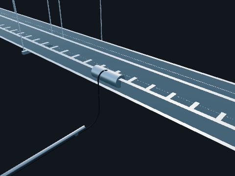
Instrument cable
Armored multi-pair cable with a shield on each pair. Carries 4 to 20 mA signals and shutdown circuits. The shields keep electrical noise off the signals.
| Basis | Manufacturer data for 18 AWG pairs: 1 pair 0.53 in OD, 12 pairs 1.21 in |
Standards: IEEE 1580, API RP 14F
Show it in 3D: Fixed platform × 5Deepwater TLP × 6
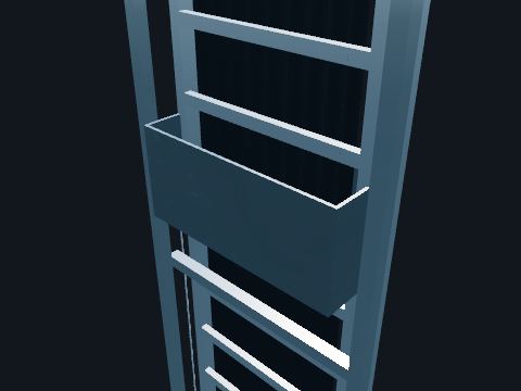
Multi-cable transit
A steel frame set in a wall, packed with rubber blocks around each cable. Lets cables pass from the tray into the electrical building or a module while the wall stays gas tight and keeps its fire rating. A compression plate squeezes the blocks tight around the cables.
| Basis | Generic offshore practice; the fire and gas rating follows the wall it is set in (Model value) |
Safety. An open or half-packed transit breaks the building’s pressurization and fire barrier: report it, and repack it after any cable work.
Standards: 30 CFR 250.114 (electrical equipment and area classification), API RP 14F (5th ed. 2008, reaffirmed 2013) / RP 14FZ (2nd ed. 2013), offshore electrical systems, per 30 CFR 250.198, API RP 14F / 14FZ (offshore electrical systems; named only), Fire and gas rating of the wall it passes through (Model value)
Show it in 3D: Fixed platform × 13Deepwater TLP × 8
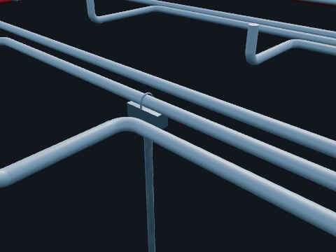
Pipe supports
Steel posts with a shoe and U-bolt under a pipe, or rods with a clevis hanging it from the deck steel above. Carry the weight of a pipe between its end connections so it does not sag, vibrate or pull on the equipment nozzles. They are spaced no farther apart than the suggested span for the pipe size.
| Basis | Suggested maximum spans for standard-weight pipe in water service, ASME B31.1 Table 121.5 (named only): 2 in 10 ft, 4 in 14 ft, 6 in 17 ft, 12 in 23 ft; support type and location: Model value |
Safety. Never climb on pipes or use a pipe support as a step or an anchor point.
Standards: ASME B31.3 (process piping; named only), ASME B31.1 Table 121.5 (suggested pipe support spacing; named only), MSS SP-58 (pipe hangers and supports; named only)
Show it in 3D: Fixed platform × 41Deepwater TLP × 49
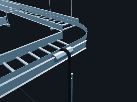
Power cable
Armored and sheathed marine power cable. Tinned copper conductors, cross-linked insulation, a braided bronze armor and an overall jacket: tough, flame-retardant and approved for offshore use.
| Basis | Manufacturer data for 600 V 3-conductor armored cable: 4 AWG 1.15 in OD, 1/0 1.54 in, 4/0 2.00 in; 5 kV 3-conductor 2/0 2.30 in |
Standards: 30 CFR 250.114 (electrical equipment and area classification), API RP 14F (5th ed. 2008, reaffirmed 2013) / RP 14FZ (2nd ed. 2013), offshore electrical systems, per 30 CFR 250.198, IEEE 1580 (marine cable), UL 1309 (marine shipboard cable)
Show it in 3D: Fixed platform × 23Deepwater TLP × 25

Rigid conduit
Threaded rigid aluminum pipe for wiring, with sealing fittings. Used for short drops to motors and instruments in classified areas. The seal stops gas or flame travelling through the conduit into or out of an enclosure.
| Basis | Manufacturer summary of the electrical code: a seal within 18 in of an enclosure that holds an arcing device. Rigid aluminum conduit 3/4 in is 1.050 in OD. |
Safety. An unpoured or cracked seal defeats the explosionproof system: report it.
Standards: 30 CFR 250.114 (electrical equipment and area classification), API RP 14F (5th ed. 2008, reaffirmed 2013) / RP 14FZ (2nd ed. 2013), offshore electrical systems, per 30 CFR 250.198, API RP 500 (3rd ed. 2012) / RP 505 (1st ed. 1997, reaffirmed 2013), area classification, per 30 CFR 250.198, NFPA 70 Articles 500-505 (hazardous locations), NFPA 70E (electrical safety in the workplace), UL 6A (rigid aluminum conduit)
Show it in 3D: Fixed platform × 26Deepwater TLP × 32
Lifting & logistics
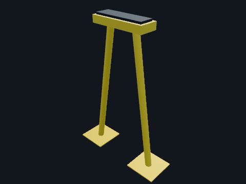
Boom rest
A padded cradle on the deck. Holds the crane boom when the crane is not working, so it cannot swing or bounce.
Standards: API Spec 2C (offshore pedestal cranes; 6th ed. 2004, per 30 CFR 250.198), API RP 2D (crane operation and maintenance; 6th ed. 2007, per 30 CFR 250.198)
Show it in 3D: Fixed platform × 2Deepwater TLP × 2
Cargo basket
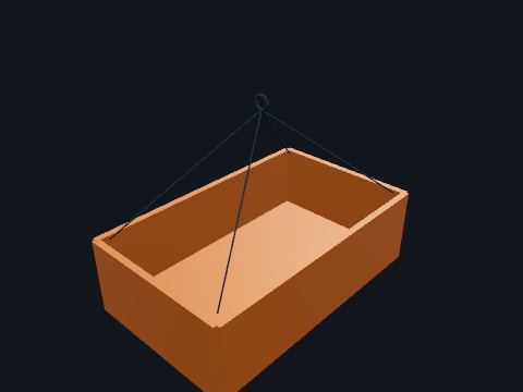
An open steel basket lifted with a sling set. Carries pipe, scaffolding and loose items.
Safety. Never ride in a cargo basket. Secure loose items so nothing can fall out during the lift.
Standards: DNV 2.7-1 (named only)
Show it in 3D: Fixed platform × 1Deepwater TLP × 1

Cargo container
An offshore container with a four-leg sling set. Carries tools, spares and supplies between the shore base and the platform.
Safety. Check the container’s inspection plate and the sling tags before every lift.
Standards: DNV 2.7-1 / EN 12079 (offshore containers; named only)
Show it in 3D: Fixed platform × 2Deepwater TLP × 1
Helideck
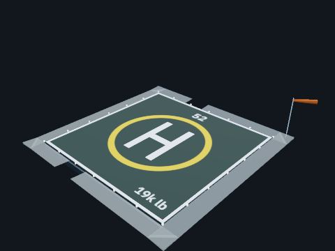
A square landing deck on top of the quarters, with a safety net, perimeter lights and a wind sock. Crew changes and urgent trips are by helicopter. The deck is sized for the largest helicopter that uses it.
| Rule | 33 CFR 143.110(b): the unprotected perimeter of the helicopter landing deck protected with a device of sufficient strength |
| Basis | The D-value and weight limit are marked on the deck; Gulf of Mexico helideck information plates list 46 to 69 ft D-values |
Safety. Approach a helicopter only when the pilot or the landing officer signals, and only in front where the pilot can see you.
Standards: 33 CFR 143.110(b) (helideck perimeter), HSAC RP 161 (Gulf of Mexico helideck practice; named only), 46 CFR 108.233, 108.235 (floating units: helicopter deck, safety net at least 1.5 m wide, main and emergency access routes)
Show it in 3D: Fixed platform × 1Deepwater TLP × 1

Laydown area
A painted area on the deck where cargo is landed and stored. Keeps loads where the deck is rated for them and out of the walkways and escape routes.
Safety. Keep escape routes and the area around ESD stations, hose reels and lifeboats clear of cargo.
Standards: API RP 2D
Show it in 3D: Fixed platform × 1Deepwater TLP × 1
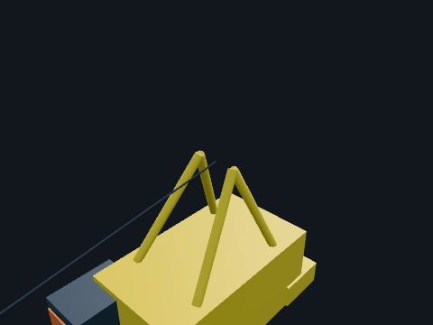
Pedestal crane
A diesel-hydraulic crane on a tall pedestal with a lattice boom. Lifts supplies, equipment and waste between boats and decks.
| Rule | 30 CFR 250.108: cranes operated and maintained per API RP 2D; cranes on platforms installed after March 17, 2003 meet API Spec 2C (6th edition, March 2004); an anti-two block device on every crane |
Safety. Stay out from under the load and the boom. Only the signal person talks to the crane operator.
Standards: 30 CFR 250.108 (cranes), API Spec 2C (offshore pedestal cranes; 6th ed. 2004, per 30 CFR 250.198), API RP 2D (crane operation and maintenance; 6th ed. 2007, per 30 CFR 250.198), 46 CFR 108.601 (floating units: cranes to API Spec 2C, 2nd ed. 1972, as the rule states)
Show it in 3D: Fixed platform × 2Deepwater TLP × 2

Tote tank
A chemical tank in a lifting frame. Carries chemicals such as methanol or corrosion inhibitor.
Safety. Keep the safety data sheet with the tank; use the right PPE when connecting or disconnecting.
Standards: 49 CFR (hazardous materials in transport, named)
Show it in 3D: Fixed platform × 2
Accommodation & buildings
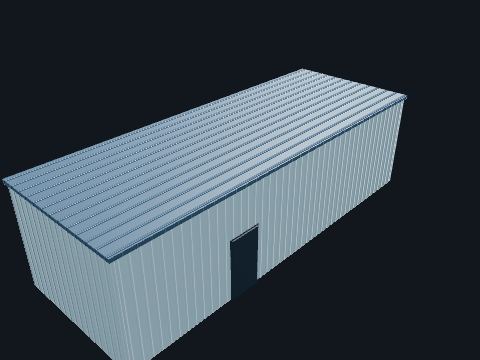
Electrical building
A steel module holding the switchgear, motor control centers, transformers, UPS and safety panels. Keeps the electrical gear dry and out of the classified area: it is placed by distance and pressurized with air from a safe location.
| Rule | 30 CFR 250.114: areas classified per API RP 500 or 505 and electrical systems installed per API RP 14F or 14FZ (named only) |
Safety. Loss of building pressurization is an alarm: find out why before opening the doors in an alarm.
Standards: 30 CFR 250.114 (electrical equipment and area classification), API RP 14F (5th ed. 2008, reaffirmed 2013) / RP 14FZ (2nd ed. 2013), offshore electrical systems, per 30 CFR 250.198, API RP 500 (3rd ed. 2012) / RP 505 (1st ed. 1997, reaffirmed 2013), area classification, per 30 CFR 250.198
Show it in 3D: Fixed platform × 1Deepwater TLP × 1
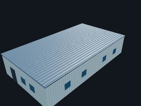
Living quarters
A two-level steel module with cabins, galley, mess, offices and the radio room. Houses the crew. It is built and placed as a refuge: away from the wells, fire-rated, with its air intake gas-monitored.
Safety. Know both ways out of your cabin and your muster station before your first night.
Standards: 33 CFR Part 143 (living quarters, named), 30 CFR 250.862(c) (gas detection exemption for quarters without a gas source)
Show it in 3D: Fixed platform × 4Deepwater TLP × 4
Drilling & well control
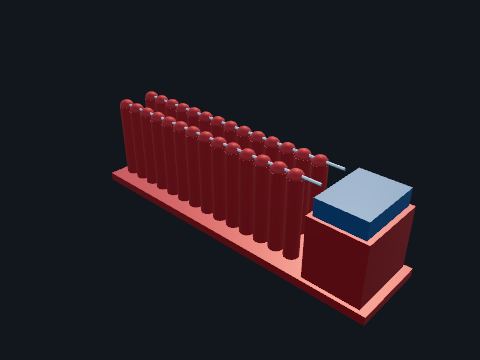
BOP closing unit (accumulator)
Bottles of nitrogen-precharged hydraulic fluid, charging pumps and a control manifold on one skid, away from the drill floor. Stores enough pressurized fluid to close the BOPs with the rig power off. The BOPs can be closed from the driller’s panel on the rig floor or from a second full control station.
| Rule | 30 CFR 250.735(a): accumulator system as specified in API Std 53 (5th ed., December 2018, per 30 CFR 250.198), named only |
| Rule | 30 CFR 250.735(c): at least two full BOP control stations; one must be on the rig floor |
Safety. The bottles hold high-pressure nitrogen and fluid: never work on a line without bleeding it down and locking out the pumps.
Standards: 30 CFR 250.735 (surface BOP system: accumulator and control stations), API Std 53 (well control equipment systems for drilling wells; 5th ed., Dec. 2018, per 30 CFR 250.198), API Spec 16D (control systems for drilling well control and diverter equipment; 2nd ed. 2004, reaffirmed 2013, per 30 CFR 250.198)
Show it in 3D: Fixed platform × 1Deepwater TLP × 1
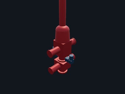
BOP stack
Blowout preventers bolted on top of the wellhead under the drill floor: an annular preventer, a blind-shear ram and two pipe rams, with the choke and kill line outlets, and the diverter housing above. Closes the well if formation fluid enters it (a kick). The annular seals around any pipe, the pipe rams seal around the drill pipe, and the blind-shear rams cut the pipe and seal the hole. The choke and kill lines let the crew circulate the kick out under control. The diverter sends a shallow gas flow overboard before the BOPs are installed.
| Rule | 30 CFR 250.733(a): a surface stack has at least four remote-controlled hydraulic BOPs: one annular, one with blind-shear rams and two with pipe rams |
| Rule | 30 CFR 250.735(d), (e): the choke line above the bottom ram; the kill line beneath at least one ram |
| Testing | 30 CFR 250.737: pressure test before 14 days have passed (blind-shear rams 30 days); low test 250 to 350 psi; function test annular and pipe rams every 7 days and shear rams every 14 days |
| Diverter | 30 CFR 250.431(a), 250.433(a): lines of at least 10 in nominal diameter for a surface wellhead; actuated at least once every 24 hours |
Safety. Only trained well-control crews operate the BOP. Stand clear of hoses, flanges and test lines while the stack is being pressure tested.
Standards: 30 CFR 250.730-250.739 (blowout preventer system), API Std 53 (well control equipment systems for drilling wells; 5th ed., Dec. 2018, per 30 CFR 250.198), API Spec 16A (drill-through equipment; 3rd ed. 2004, reaffirmed 2010, per 30 CFR 250.198), 30 CFR 250.430-250.433 (diverter system)
Show it in 3D: Fixed platform × 1Deepwater TLP × 1
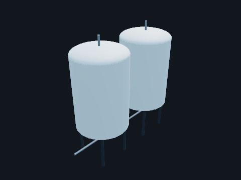
Bulk tanks
Tall pressurized tanks for dry powders: barite for weighting the mud and cement. Store the powders in bulk; air pushes them through pipes to the mixing hopper or the cement unit.
| Rule | 30 CFR 250.458: enough mud and mud materials on hand for the expected conditions, with a daily inventory; drilling stops if they run short |
Safety. Tanks are pressure vessels while they transfer: check the gauge before opening a hatch.
Standards: 30 CFR 250.458 (quantities of drilling fluids and materials)
Show it in 3D: Fixed platform × 2Deepwater TLP × 2
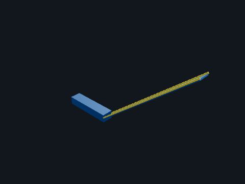
Catwalk and V-door ramp
The ramp from the pipe deck up to the V-door, the opening in the front of the derrick at drill floor level. Pipe is slid up the ramp to the floor and back down; the ramp is also a way off the drill floor.
Standards: 33 CFR 143.110 (guards and rails)
Show it in 3D: Fixed platform × 1Deepwater TLP × 1
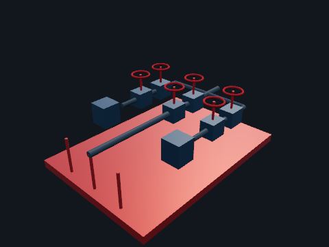
Choke manifold
A skid of high-pressure valves and adjustable chokes connected to the BOP choke line. During well control the chokes hold back pressure on the well while the kick is circulated out, and send the returns to the mud gas separator.
| Rule | 30 CFR 250.736(a): a choke manifold suitable for the anticipated surface pressures |
| Testing | 30 CFR 250.737(b): high-pressure test at the rated working pressure or 500 psi above MASP |
Standards: 30 CFR 250.736 (choke manifold), API Spec 16C (choke and kill systems; 1st ed. 1993, reaffirmed 2010, per 30 CFR 250.198), API Std 53 (well control equipment systems for drilling wells; 5th ed., Dec. 2018, per 30 CFR 250.198)
Show it in 3D: Fixed platform × 1Deepwater TLP × 1
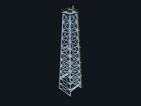
Derrick
The tall four-legged steel lattice tower over the well, with the crown block on top and the racking board part way up. Holds the crown block and the traveling equipment so the rig can lift the whole drill string or casing string, and holds the drill pipe stood back in stands on the racking board while the bit is changed.
| Standard | API Spec 4F (drilling structures) and API RP 4G (inspection and maintenance), named only; neither is incorporated in 30 CFR 250 |
Safety. Climbing the derrick needs a full-body harness on the ladder fall arrest. Anything taken aloft is tethered or has secondary retention: a dropped object from the derrick can kill on the floor below.
Standards: API Spec 4F (drilling and well servicing structures; named only, not incorporated in 30 CFR 250), API RP 4G (inspection and maintenance of drilling structures; named only, not incorporated in 30 CFR 250)
Show it in 3D: Fixed platform × 1Deepwater TLP × 1
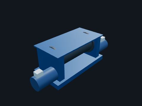
Drawworks
The main hoist: a large drum, its brakes and motors at the back of the drill floor. Spools the drilling line that runs up to the crown block and down to the traveling block, raising and lowering the drill string; its brakes hold the full hook load.
Safety. Keep clear of the drum and the fast line; a parting line under load whips across the floor.
Standards: 30 CFR 250 Subpart D (oil and gas drilling operations)
Show it in 3D: Fixed platform × 1Deepwater TLP × 1
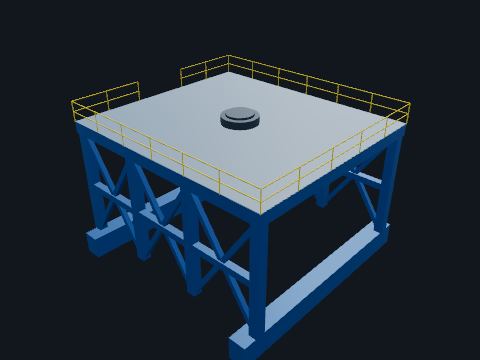
Drill floor and substructure
The steel structure that lifts the drill floor high above the deck, and the floor itself with the rotary table at the well centre. Leaves room under the floor for the BOP stack and the diverter on top of the wellhead, carries the derrick and the weight of the pipe in the hole, and is where the crew makes up and breaks out pipe.
| Rule | 30 CFR 250.723(b): an emergency shutdown station for the production system near the driller’s console |
| Rule | 30 CFR 250.456(c), (f): the hole-fill schedule and the maximum safe shut-in pressures are posted near the driller’s console |
Safety. The drill floor is a red zone while pipe is moving: only the crew needed for the job, and nobody under a suspended load or in the swing of the tongs.
Standards: 30 CFR 250 Subpart D (oil and gas drilling operations), 30 CFR 250.723(b) (ESD station near the driller’s console), 30 CFR 250.456(c), (f) (postings near the driller’s console), API Spec 4F (drilling and well servicing structures; named only, not incorporated in 30 CFR 250)
Show it in 3D: Fixed platform × 1Deepwater TLP × 1

Driller’s cabin
The enclosed control cabin on the drill floor with windows onto the well centre and the V-door. The driller runs the drawworks, top drive, mud pumps and the BOP and diverter panels from here and watches the pit volume, flow and gas readings for the first sign of a kick.
| Rule | 30 CFR 250.457: pit level, trip volume, return flow and gas-in-returns indicators on the rig floor; the pit level indicator has visual and audible warnings |
| Rule | 30 CFR 250.431(c): one diverter control station on the drill floor and another away from it |
Standards: 30 CFR 250.457 (drilling fluid monitoring on the rig floor), 30 CFR 250.735(c) (BOP control station on the rig floor), 30 CFR 250.431(c) (diverter control station on the drilling floor)
Show it in 3D: Fixed platform × 1Deepwater TLP × 1
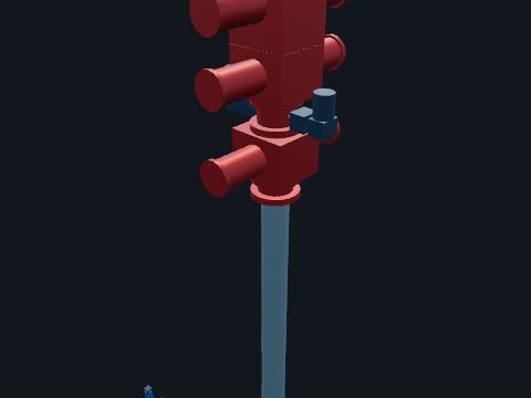
Drilling riser
The high-pressure riser from the seabed wellhead up to the surface BOP stack under the drill floor, on the well being drilled. Brings the well up to the BOPs on the platform. With a surface BOP on a floating production facility it is dual bore wherever hydrocarbons may be exposed to the well: an inner riser inside an outer riser, with the space between them watched for pressure.
| Rule | 30 CFR 250.733(b)(2): with a surface BOP on a floating production facility, risers installed after July 28, 2016 are dual bore before drilling or operating in any hole section where hydrocarbons are, or may be, exposed to the well; the annulus between the risers is monitored for pressure |
Standards: 30 CFR 250.733(b)(2) (dual bore riser with the annulus monitored), API RP 2RD (risers for floating production systems and TLPs; 1st ed. June 1998, reaffirmed May 2006, errata June 2009, per 30 CFR 250.198), 30 CFR 250.733(b)(1), 250.734(a)(1) (surface BOP on a floating production facility)
Show it in 3D: Deepwater TLP × 1
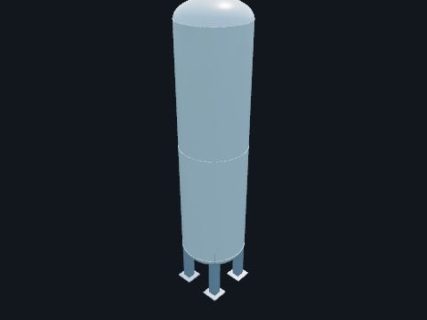
Mud gas separator
A tall open-bottom vessel (often called the poor boy degasser) next to the shakers. Takes the mud and gas coming back through the choke during well control, lets the gas break out and vents it up a line to a safe height, and sends the mud on to the shakers.
| Rule | 30 CFR 250.456(g): an operable drilling fluid-gas separator and degasser before drilling starts |
Standards: 30 CFR 250.456(g) (drilling fluid-gas separator and degasser)
Show it in 3D: Fixed platform × 1Deepwater TLP × 1
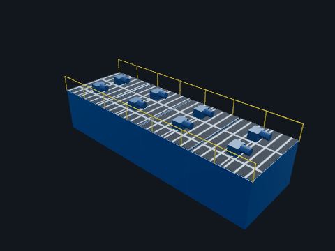
Mud pits
Steel tanks for the drilling mud, with agitators and grating on top. Store, mix and treat the mud. The active pit volume is watched closely: a gain means fluid is coming into the well.
| Rule | 30 CFR 250.457(a): pit level indicator with visual and audible warnings |
| Rule | 30 CFR 250.459: mud-handling areas classified per API RP 500; where dangerous concentrations of combustible gas may accumulate, ventilation able to replace the air once every 5 minutes, and gas detectors (except in open, naturally ventilated areas) tested quarterly |
| Rule | 30 CFR 250.456(i): mud tested at least once each tour for density, viscosity and gel strength |
Safety. Pits can hold gas and H2S: gas test before entry and treat every pit as a confined space.
Standards: 30 CFR 250.455-250.459 (drilling fluids), API RP 500 (3rd ed. 2012), area classification, per 30 CFR 250.198
Show it in 3D: Fixed platform × 1Deepwater TLP × 1
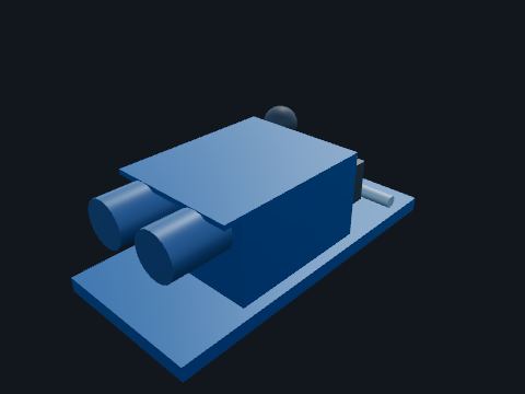
Mud pump
A large triplex (three-cylinder) piston pump with its motors on a skid. Pumps drilling mud down the drill pipe at high pressure. The mud cools the bit, carries the cuttings back up and holds the formation pressure back.
Safety. Discharge lines run at thousands of psi: stay out of the line of fire of the pulsation dampener and the relief valve, and lock out before opening a fluid end.
Standards: 30 CFR 250 Subpart D (oil and gas drilling operations)
Show it in 3D: Fixed platform × 3Deepwater TLP × 3
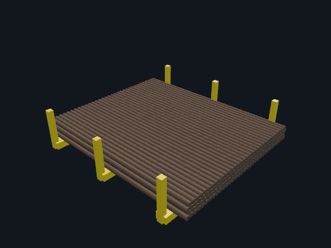
Pipe deck and racks
Racks on the pipe deck holding drill pipe and casing. Store tubulars delivered by supply boat until they are picked up the catwalk to the drill floor.
Safety. Pipe can roll: chock every layer, and never stand between a moving joint and a fixed object.
Standards: 30 CFR 250 Subpart D (oil and gas drilling operations)
Show it in 3D: Fixed platform × 2Deepwater TLP × 2
Rig power module
An enclosed module holding the rig’s diesel engines and generators and the drives (SCR or VFD) that run the rig motors. Makes the power for the drawworks, top drive, mud pumps and the rest of the rig, separate from the platform’s own generators. Some platform rigs instead take power from the platform.
| Rule | 30 CFR 250.405: every diesel engine on the rig has an air intake device to shut it down if it runs away; automatic where the engine is not continuously attended |
Safety. Engine room: hot surfaces, rotating parts and noise. Hearing protection, and no entry with the engines running unless you are on the engine crew.
Standards: 30 CFR 250.114 (electrical equipment and area classification), API RP 14F (5th ed. 2008, reaffirmed 2013) / RP 14FZ (2nd ed. 2013), offshore electrical systems, per 30 CFR 250.198, 30 CFR 250.405 (diesel engine air intake shutdown devices on the rig)
Show it in 3D: Fixed platform × 1Deepwater TLP × 1

Rig skid beams
Two heavy box beams on the deck either side of the well bay, with the rig’s skid base riding on them. Hydraulic jacks push the rig along the beams and the skid base slides across them, so the drill floor can be centered over any well slot without lifting the rig.
| Rule | 30 CFR 250.723(c)(2): every producible well in the affected wellbay is shut in, below the surface and at the wellhead, while the rig is skidded between wells |
Safety. Nobody stands on or beside the skid beams while the rig moves; the jacks and the moving base are crush points.
Standards: 30 CFR 250 Subpart D (oil and gas drilling operations), 30 CFR 250.723 (drilling on a platform with producing wells; (c) shut-in while the rig moves), API Spec 4F (drilling and well servicing structures; named only, not incorporated in 30 CFR 250)
Show it in 3D: Fixed platform × 1Deepwater TLP × 1
Shale shakers
Vibrating screens where the mud first comes back from the well. Shake the rock cuttings out of the mud before it goes back to the pits. The cuttings are bagged for shipping to shore or treated for discharge.
| Rule | 30 CFR 250.490(a), (j)(2): where H2S is present or unknown, sensors at the bell nipple, the possum belly and the shale shaker, among others |
Safety. The shaker house is noisy and the mud may carry gas: hearing protection, and watch the gas readings.
Standards: 30 CFR 250.459 (drilling fluid-handling areas), 30 CFR 250.490(j) (hydrogen sulfide sensors)
Show it in 3D: Fixed platform × 1Deepwater TLP × 1
Top drive and traveling block
A large motor hung from the traveling block that turns the drill string from the top, running on a guide rail at the back of the derrick. Rotates the pipe and pumps mud down it through the same connection, so the crew can drill a whole stand at a time and circulate or close the internal BOP while pulling out of the hole.
Safety. Stay out of the path of the traveling equipment; the top drive and its links move fast and without warning when the driller hoists.
Standards: 30 CFR 250 Subpart D (oil and gas drilling operations)
Show it in 3D: Fixed platform × 1Deepwater TLP × 1
Hull, tendons & risers

Hull column
One of the four large round steel columns of the floating hull, painted dark below the waterline and with draft marks on the outside. The columns float the platform and carry the deck on their tops. Inside are watertight compartments for ballast water, voids and machinery, so the crew can trim the hull and keep it level as loads change.
| Rule | 33 CFR 140.10: a floating OCS facility includes tension leg platforms; 33 CFR 143.120(b): it meets 46 CFR subchapters F and J and 46 CFR Part 108 |
| Rule | 46 CFR 108.301: stability to the Subchapter S rules that apply to mobile offshore drilling units, including 46 CFR Part 174 Subpart C |
| Standard | API RP 2T (3rd ed., July 2010, reaffirmed June 2015, per 30 CFR 250.198), named only |
Safety. Column voids and ballast tanks are confined spaces: entry only with a permit, a gas test and a standby person.
Standards: 30 CFR 250 Subpart I (platforms and structures), 30 CFR 250.910(b) (Platform Verification Program: the whole new floating platform, with its risers, tensioning systems, foundations and tethers), API RP 2T (tension leg platforms; 3rd ed. July 2010, reaffirmed June 2015, per 30 CFR 250.198), 33 CFR 143.120 (floating OCS facilities: Coast Guard vessel rules in 46 CFR apply), 46 CFR 108.301 (stability, through 46 CFR Part 174 Subpart C)
Show it in 3D: Deepwater TLP × 4
Ring pontoon
The rectangular steel box that joins the bottoms of the four columns in a ring. Adds buoyancy low in the hull and ties the columns together; with this model’s sizes the submerged columns displace about three times as much water as the pontoons. The tendon porches are on the outside of the columns at the pontoon.
| Rule | 30 CFR 250.910(b): every new floating platform is in the Platform Verification Program, the whole platform including its risers, foundations and tethers |
Standards: 30 CFR 250 Subpart I (platforms and structures), 30 CFR 250.910(b) (Platform Verification Program: the whole new floating platform, with its risers, tensioning systems, foundations and tethers), API RP 2T (tension leg platforms; 3rd ed. July 2010, reaffirmed June 2015, per 30 CFR 250.198), 33 CFR 143.120 (floating OCS facilities: Coast Guard vessel rules in 46 CFR apply), 46 CFR 108.301 (stability, through 46 CFR Part 174 Subpart C)
Show it in 3D: Deepwater TLP × 4

Riser tensioner
A ring of hydraulic cylinders under the well bay deck, clamped to a production riser. Pulls up on the riser with a nearly constant force while the hull moves a few feet relative to it, so the riser stays in tension. Nitrogen-charged accumulators keep the force steady.
| Rule | 30 CFR 250.910(b)(1)(i): drilling, production and pipeline risers and riser tensioning systems are part of the Platform Verification Program |
Safety. Tensioners store a great deal of energy in nitrogen and hydraulic pressure: work on one only under a permit with the riser load taken by another means.
Standards: 30 CFR 250.910(b) (Platform Verification Program: the whole new floating platform, with its risers, tensioning systems, foundations and tethers), API RP 2RD (risers for floating production systems and TLPs; 1st ed. June 1998, reaffirmed May 2006, errata June 2009, per 30 CFR 250.198)
Show it in 3D: Deepwater TLP × 13

Steel catenary riser
A steel pipeline that hangs from a flexible joint on the hull in a long curve down to the seabed. Carries the platform’s oil or gas export, or a subsea tieback, between the seabed pipeline and the deck. The curve lets it absorb the hull’s offset without a joint at the seabed.
| Rule | 30 CFR 250.1002(b)(5): pipeline risers for tension leg platforms are designed to API RP 2RD (1st ed., June 1998, reaffirmed May 2006, errata June 2009, per 30 CFR 250.198) |
| Rule | 30 CFR 250.1007(a)(4)(ii): the riser application gives the design fatigue life and a vortex-induced vibration analysis |
Standards: 30 CFR 250.1002(b)(5) (pipeline risers on TLPs and other floating platforms to API RP 2RD), API RP 2RD (risers for floating production systems and TLPs; 1st ed. June 1998, reaffirmed May 2006, errata June 2009, per 30 CFR 250.198), 30 CFR 250 Subpart J (pipelines and pipeline rights-of-way), 30 CFR 250.1004(b)(3) (departing pipelines: high- and low-pressure sensors)
Show it in 3D: Deepwater TLP × 2

Tendon
A vertical string of thick steel pipe, about 28 in across, from the hull keel to the seabed. Three hang at each corner. Holds the hull down below the draft it would float at, so the spare buoyancy keeps every tendon in tension. The hull can sway sideways a little but hardly moves up and down, which is why the wells can have dry trees on deck.
| Rule | 30 CFR 250.910(b)(1)(iv): mooring or tethering systems are part of the Platform Verification Program |
| Rule | 30 CFR 250.919(a): an in-service inspection report each year by November 1, covering the pertinent components of the mooring system of floating platforms |
| Standard | API RP 2T (3rd ed., July 2010, reaffirmed June 2015, per 30 CFR 250.198), named only |
Standards: 30 CFR 250.910(b) (Platform Verification Program: the whole new floating platform, with its risers, tensioning systems, foundations and tethers), API RP 2T (tension leg platforms; 3rd ed. July 2010, reaffirmed June 2015, per 30 CFR 250.198), 30 CFR 250.919 (annual in-service inspection report, due November 1)
Show it in 3D: Deepwater TLP × 12
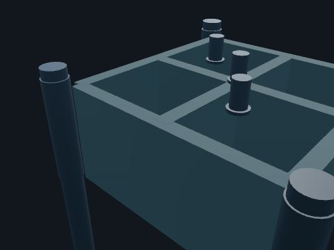
Tendon foundation
A steel template on the seabed under each corner, held by piles driven deep into the seabed, with receptacles for the tendon bottoms. Anchors the tendons. The piles resist the steady upward pull of the hull.
| Rule | 30 CFR 250.910(b)(1)(iii): foundations, foundation pilings and templates are verified |
| Rule | 30 CFR 250.907(a): for tension leg platforms no foundation pile may be more than 500 ft from a soil boring |
Standards: 30 CFR 250.907(a) (TLP piles within 500 ft of a soil boring), 30 CFR 250.910(b) (Platform Verification Program: the whole new floating platform, with its risers, tensioning systems, foundations and tethers), API RP 2T (tension leg platforms; 3rd ed. July 2010, reaffirmed June 2015, per 30 CFR 250.198)
Show it in 3D: Deepwater TLP × 4

Tendon porch
A heavy bracket on the outside of a column at the keel holding the top connector of one tendon. Transfers the pull of the tendon into the hull. Load cells on the instrumented tendons report their tension to the control room (which tendons are instrumented: Model value).
| Rule | 30 CFR 250.911(d): the verification schedule breaks out the tendon systems |
Standards: 30 CFR 250.910(b) (Platform Verification Program: the whole new floating platform, with its risers, tensioning systems, foundations and tethers), API RP 2T (tension leg platforms; 3rd ed. July 2010, reaffirmed June 2015, per 30 CFR 250.198)
Show it in 3D: Deepwater TLP × 4

Top-tensioned production riser
A steel riser pipe running straight down from the dry tree on the well bay deck to the wellhead on the seabed, one per well. Carries the well’s tubing and casing strings up to the deck, so the tree, the master valves and the SSV are on the platform where people can reach them. Its tensioner holds it up so it does not buckle.
| Rule | 30 CFR 250.800(c)(2): production risers meet API RP 2RD; single-bore production risers may not be installed from floating production facilities |
| Rule | 30 CFR 250.814(a): the surface-controlled subsurface safety valve is at least 100 ft below the mudline |
Safety. A riser holds well pressure. Keep clear of the tensioner and the tree during well work unless you are part of the job.
Standards: 30 CFR 250.800(c)(2) (production risers to API RP 2RD; no single-bore production risers from floating production facilities), API RP 2RD (risers for floating production systems and TLPs; 1st ed. June 1998, reaffirmed May 2006, errata June 2009, per 30 CFR 250.198), 30 CFR 250.910(b) (Platform Verification Program: the whole new floating platform, with its risers, tensioning systems, foundations and tethers)
Show it in 3D: Deepwater TLP × 12
Safety & PPE
Flame-resistant clothing
Coveralls or shirt and trousers made of flame-resistant fabric, worn as the daily work uniform on most production platforms. Limits burn injury from a flash fire and does not continue to burn after the flame is gone. Arc-rated clothing is chosen separately for electrical work.
Standards: 33 CFR 142.36 (protective clothing), NFPA 2112 (flame-resistant garments; named only), NFPA 70E (arc-rated clothing for electrical work)
Reference entry, not built in a facility yet
Full-body harness and lanyard
A harness with a lanyard or self-retracting line clipped to a lifeline or fixed anchorage. Arrests a fall where there is a fall hazard (the rule threshold is in 33 CFR 142.42), for example over the side, on the flare boom or at an open grating panel.
Standards: 33 CFR 142.42 (safety belts and lifelines), ANSI A10.14 (named in the rule), ANSI/ASSP Z359 series (named only)
Reference entry, not built in a facility yet
Hard hat
Head protection rated for impact, worn everywhere outside the quarters. Protects against falling objects during lifts and overhead work and against bumps on low piping.
Standards: 33 CFR 142.30 (head protection), ANSI Z89.1 (named in the rule)
Reference entry, not built in a facility yet
Personal H2S monitor
A small clip-on detector worn in the breathing zone on facilities where hydrogen sulfide may be present. Alarms the wearer when H2S reaches its set points so they can leave upwind or crosswind to a safe briefing area.
Standards: 30 CFR 250.490 (hydrogen sulfide)
Reference entry, not built in a facility yet
Safety glasses, goggles and face shield
Impact-rated eye protection; goggles or a face shield are added for chemicals, grinding and welding. Protects the eyes from chips, spray from a leaking fitting, and chemicals such as glycol, methanol and corrosion inhibitor.
Standards: 33 CFR 142.27 (eye and face protection), ANSI Z87.1 (named in the rule)
Reference entry, not built in a facility yet
Safety-toe boots
Protective footwear worn on decks. Protects the feet from dropped loads and crush points.
Standards: 33 CFR 142.33 (foot protection), ANSI Z41 (named in the rule; since replaced by ASTM F2413)
Reference entry, not built in a facility yet
Self-contained breathing apparatus (SCBA)
A full-face mask supplied from a compressed-air cylinder carried on the back. Escape units are smaller and are for getting out only. Lets a trained person work in, rescue from, or escape an atmosphere that is unsafe to breathe, such as an H2S release.
Standards: 33 CFR 142.39 (respiratory protection), 30 CFR 250.490 (hydrogen sulfide), ANSI Z88.2 (named in the rule), 42 CFR Part 84 (respirator approval)
Reference entry, not built in a facility yet
Work vest (personal flotation device)
A buoyant vest worn while working where a fall into the water is likely, such as on the boat landing, the cellar deck edge or during personnel transfers. Keeps a person afloat after a fall into the sea until recovered. Not needed while a safety belt and lifeline are in use.
Standards: 33 CFR 142.45 (personal flotation devices), 33 CFR 146.20 (work vests, named)
Reference entry, not built in a facility yet
Test & maintenance equipment
Multimeter and voltage tester
A hand meter rated for the measurement category of the circuit, with insulated test leads. Used to prove a circuit is dead before work (test the tester on a known live source before and after), and to check control circuits.
Standards: NFPA 70E (electrical safety in the workplace), UL 61010-1 (test instrument safety; named only), 33 CFR 142.90 (lockout and tagout)
Reference entry, not built in a facility yet
Portable multi-gas detector
A hand-held meter that reads flammable gas, oxygen, H2S and often carbon monoxide. Used to test the atmosphere before and during hot work and confined-space entry, and to check that equipment is gas-free after isolation and purging. Bump-tested before use.
Standards: 30 CFR 250.113 (welding, burning and hot tapping), 30 CFR 250.490 (hydrogen sulfide)
Reference entry, not built in a facility yet
Relief valve test stand
A bench with a pressure source and gauges used to pop-test relief valves removed from service, or a lift-assist kit used to test them in place. Confirms each PSV opens at its set pressure and reseats tight before it goes back in service.
Standards: 30 CFR 250.880 (safety system testing), API Std 527 (seat tightness), API Std 520 Part II (installation; named only)
Reference entry, not built in a facility yet
Ultrasonic thickness gauge
A hand-held instrument that measures remaining wall thickness of pipe and vessels from the outside. Used on inspection rounds to track corrosion and erosion at elbows, tees and vessel shells so a thin spot is found before it leaks.
Standards: API 510 (pressure vessel inspection), API 570 (piping inspection)
Reference entry, not built in a facility yet
Communications & control networks
Marine VHF radio
Fixed and hand-held radios on marine channels, used to talk with supply boats, standby vessels and helicopters. Coordinates crane lifts to boats, personnel transfers and emergency response.
Standards: 47 CFR Part 80 (stations in the maritime services)
Reference entry, not built in a facility yet
Process control system (PCS)
The programmable controllers and operator screens that run the process: level and pressure control, pump start and stop, alarms. Keeps the process at its set points. It is separate from the safety shutdown system so a control failure cannot defeat a shutdown.
Standards: ISA-5.1 (instrument symbols and identification), ISA-84 / IEC 61511 (safety instrumented systems; separation from control)
In the model: Modeled as Process control panel Fixed platform × 1Deepwater TLP × 1
The PCS panel in the electrical building is the modeled item.
Public address and general alarm
Loudspeakers, alarm horns and strobe lights across the platform, driven from the control room and from manual stations. Sounds the muster signal and the abandon signal, and carries spoken instructions. In noisy areas the strobes carry the alarm.
Standards: 33 CFR 146.110 (alarm signals), 33 CFR 146.125 (drills)
Reference entry, not built in a facility yet
SCADA and remote monitoring link
The data link (radio, microwave, satellite or fiber) between the platform control system and the operator's onshore control center. Sends alarms, pressures and flows to shore and lets shore personnel see the platform state. Shutdown logic stays on the platform.
Standards: API RP 1165 (SCADA displays; named only), API Std 1164 (pipeline control system cybersecurity; named only)
Reference entry, not built in a facility yet