4-column TLP | 3,000 ft (914 m) water | platform rig | 12 dry trees | 150 POB
Deepwater tension leg platform
A floating drilling and production platform in about 3,000 ft of water in the deepwater U.S. Gulf of Mexico. Four 72 ft steel columns on a ring pontoon carry a three-level deck box about 280 ft square. Twelve steel tendons pull the hull down to piled foundations on the seabed, so it hardly heaves and the wells end in dry trees on deck, reached through top-tensioned risers. A platform rig on the upper deck drills and works over the wells. Separators, an electrostatic treater, glycol dehydration and turbine-driven compressors handle about 100,000 barrels of oil and 150 million standard cubic feet of gas a day, which leave by steel catenary risers. Three gas turbine generators make the power; quarters for 150 people with the helideck on top stand at the west end, away from the well bay, the process and the flare.
Open this facility in 3DAll facilities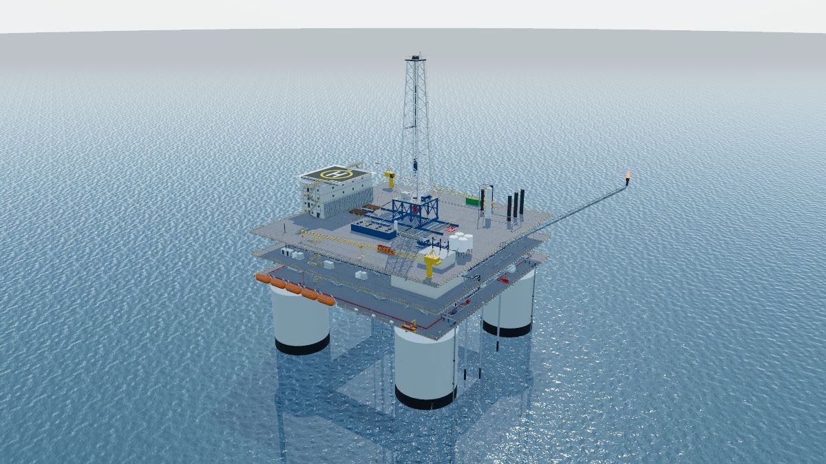
How it is arranged
Generic facility for training. It is not a real platform, field or operator. Hull, tendon, riser and foundation sizes sit inside ranges reported for Gulf of Mexico TLPs in the trade press and in BSEE and MMS reports; drilling equipment sizes come from a Gulf TLP platform rig specification sheet where the part says so; process sizes are worked out for about 100,000 barrels of oil and 150 million standard cubic feet of gas a day and are model values. Lifesaving, helideck and crane arrangements follow the Coast Guard rules for floating OCS facilities (33 CFR 143.120 and 46 CFR part 108).
Walk through it
The guided tour in the trainer stops at each of these, highlights the equipment and explains it.
- This is a tension leg platform in about 3,000 ft of water. It floats: four round steel columns, 72 ft across, give it buoyancy. Steel tendons pull the hull down below the depth it would float at on its own, so it is held in place instead of riding the waves. X-ray is on so you can see below the sea.
- A ring pontoon joins the columns at the keel, about 95 ft below the sea (Model value). Most of the buoyancy below the waterline is in the pontoon and the lower columns; ballast and void compartments inside let the crew trim the hull.
- Twelve tendons, three at each corner, run about 2,900 ft down to the seabed. Each is 28 in steel pipe in segments (250 ft here; 100 to 300 ft is typical) joined by mechanical connectors. The hull’s spare buoyancy keeps every tendon in tension, so the platform hardly heaves; it can still drift sideways a little, and it sits slightly deeper when it does (set-down).
- At the foot of each column the tendon top connectors sit in porches. Load cells on the instrumented tendons report their tension to the control room.
- On the seabed each corner has a foundation template, 60 ft square, held down by four 72 in piles about 427 ft long. For a TLP no foundation pile may be more than 500 ft from a soil boring (30 CFR 250.907(a)). The whole platform, tendons and foundations included, goes through the Platform Verification Program (30 CFR 250.910(b)).
- Each producing well has a top-tensioned riser from its seabed wellhead straight up to the well bay. Single-bore production risers are not allowed from a floating production facility (30 CFR 250.800(c)(2)), so each riser has two casings around the tubing.
- Under the well bay each riser hangs from a tensioner: four hydraulic cylinders that keep a steady pull on the riser while the hull moves. Their stroke is short because a TLP hardly heaves.
- Because the hull hardly moves, the wells can end on deck in dry trees, as on a fixed platform: master valves, wing valve, choke and swab valve you can walk up to. Twelve of the 24 slots have wells; one more slot is being drilled.
- The red actuator works the surface safety valve. Control pressure holds it open; any shutdown vents that pressure and a spring closes it within 45 seconds (30 CFR 250.821(b)). The SCSSV, held at least 100 ft below the mudline, closes after it.
- The wellhead control panel holds every SSV and SCSSV open with hydraulic pressure. Every shutdown signal on the platform ends here, by venting a pilot.
- Flowlines from the trees run east in lanes to the manifold. Each well can be lined up to the production header or, one at a time, to the test header for its well test.
- The platform rig stands on the upper deck. Its derrick is 170 ft high and rated for 1,250,000 lb, but on this hull the static hook load is limited to 850,000 lb and the setback to 585,000 lb: what the hull and tendons are built to carry sets the limit, not the derrick.
- The rig skids along its beams, and its skid base slides across them, to reach any of the 24 slots through the well bay hatch. While it moves, every producible well in the affected well bay is shut in, below the surface and at the wellhead (30 CFR 250.723(c)).
- On a TLP the BOP stack sits at the surface, under the drill floor, on top of the drilling riser. A floating production facility installed after April 29, 2021 with a surface BOP needs at least five BOPs: an annular, two pipe rams and two shear rams, the non-sealing casing shear below the sealing blind-shear (30 CFR 250.733(b)(1), 250.734(a)(1)). The diverter vent lines are 12 in (30 CFR 250.431(a)).
- The drilling riser joins the seabed wellhead of the well being drilled to the BOP. It is dual bore, a 21 in outer riser around an 11-3/4 in inner riser, with the annulus between them watched for pressure (30 CFR 250.733(b)(2)). An independent, automatic and continuous system records real-time data from the BOP controls and the mud circulating system (30 CFR 250.724(a)).
- The drilling riser has its own tensioner, six cylinders with about 1,000,000 lb of capacity, so the riser stays straight as the hull moves.
- The BOP closing unit stores hydraulic fluid under nitrogen pressure, enough to close the BOPs with the rig power off.
- If the well kicks, the crew shuts it in and circulates the influx out through the choke line and this choke manifold, holding back pressure on the well. The returns go to the mud gas separator, which vents the gas high.
- Three triplex mud pumps send drilling mud up the standpipe, through the rotary hose and the top drive and down the drill string.
- Returning mud crosses four shale shakers, which screen out the cuttings, then goes back to the pits, about 1,430 bbl in all. A pit gain on the driller’s screens means the well may be flowing.
- The HP separator, 12 ft across and 56 ft long, splits the well stream into gas, oil and water. Its level and pressure trips, and the relief valve on top, protect it if the controls fail.
- The electrostatic treater takes the oil from the LP separator. The electric field between its grids makes the last small water drops merge and settle, so the oil meets the pipeline’s water limit.
- Sales oil is measured in the LACT unit, then three export pumps push it into the oil export riser.
- Oil and gas leave through steel catenary risers hung from flex joints on the columns. Each curves down to touch the seabed far from the hull and runs on as a pipeline. Pipeline risers on a TLP are designed to API RP 2RD (named only; 30 CFR 250.1002(b)(5)).
- Each export riser has a shutdown valve where it comes on board. The ESD system closes it, so a fire on the platform cannot draw on the pipeline’s inventory. A departing pipeline is also protected by high- and low-pressure sensors (30 CFR 250.1004(b)(3)).
- The tall tower on the upper deck is the glycol contactor. Wet gas rises against triethylene glycol, which soaks up the water so the gas will not form hydrates in the pipeline.
- Two export compressors, each driven by a 5,000 hp gas turbine, raise the dry gas to the export pipeline pressure. The flash gas compressor next to them, with a 2,000 hp electric motor, brings the low-pressure gas back up so it is sold instead of flared.
- Three gas turbine generators make the power at 13.8 kV; two carry the load and one stands by. The switchgear, transformers and motor control centers are in the electrical building. The emergency diesel generator and the UPS keep the safety systems alive if all three stop.
- The flare burns relieved and blown-down gas at the end of a boom about 160 ft long (Model value) on the east edge, the far side from the quarters.
- Two fire pumps of 5,000 gpm draw sea water up their caissons: one diesel, one electric, so they are independently driven (46 CFR 108.415). On a floating facility the firewater system follows the Coast Guard rules (30 CFR 250.859(b)).
- A deluge ring over the well bay can drench the trees with water. Detectors in the well bay, a fusible loop and ESD stations at every stair guard the wells.
- The quarters for 150 people, four levels with the helideck on top, are at the west end, behind a fire wall, as far as the deck allows from the wells, the rig and the process.
- The helideck is sized for a medium twin-engine helicopter with 19 passengers. A safety net at least 1.5 m wide runs round the unprotected edge, and there is a main and an emergency access route (46 CFR 108.235(e), (f)).
- Ten 33-person lifeboats hang on the lower deck, five on each side, so the boats on either side alone hold everyone on board (46 CFR 108.525(a)(1)). Float-free liferafts hold everyone again (108.525(a)(2)), and the rescue boat picks people out of the water (108.560).
- Two pedestal cranes with 180 ft booms lift cargo between the supply boats and the decks; cranes on a floating unit are designed to API Spec 2C (named only; 46 CFR 108.601). That is the tour; try Walk the platform or open the drawings next.
Equipment on this facility
Each item links to its entry in the equipment reference. In the trainer, click any of them to see what it does, its ratings and its safety note.
Deck framing × 4Deck grating × 5Deck leg × 2Deck plate × 1Disposal caisson × 1Pump caisson × 2Sea surface × 1Seabed (mudline) × 1Skid base × 2Stair × 6Sump pile × 1Vessel platform × 1Water column × 1Dry tree (Christmas tree) × 12Production choke × 12Surface safety valve (SSV) × 12Wellhead × 12Electrostatic treater × 1Exhaust stack × 2Flare knockout drum × 1Fuel gas filter × 2Fuel gas heater × 1Fuel gas scrubber × 1Gas flotation unit × 1Gas scrubber × 1Glycol contactor × 1Glycol filter × 2Glycol reboiler × 1Glycol surge drum × 1Hydrocyclone × 2Separator × 2Still column × 1Test separator × 1Charge pump × 2Glycol pump × 2Instrument air package × 1Oil export pump × 3Reciprocating compressor package × 1Turbine-driven compressor × 2Water maker × 1Check valve × 12Control valve × 1Flowline × 24LACT unit × 1Manual valve × 24Pig launcher × 2Pipeline riser × 2Pressure safety valve (PSV) × 4Process piping × 63Relief and flare piping × 5Riser clamp × 2Shutdown valve (SDV) × 3Chemical injection skid × 1Control tubing × 9Differential pressure transmitter × 1Heated instrument enclosure × 1Impulse tubing × 1Instrument stand × 1Level transmitter (guided wave radar) × 1Magnetic level gauge × 1Orifice meter × 1Pressure transmitter × 1Process control panel × 1Temperature transmitter × 1Wellhead control panel × 1Combustible gas detector × 8Deluge system × 1Deluge valve × 1ESD station × 8Eyewash station × 1Fire and gas panel × 1Fire hose reel × 3Fire wall × 1Fire water main × 2Fire water monitor × 2Fire water pump × 2Flame detector × 4Flare boom × 1Flare tip × 1Fusible plug loop (TSE) × 1Guard rail × 26Inflatable liferaft × 6Lifeboat (survival craft) × 10Lifeboat davit × 10Muster station × 2Obstruction light × 1Rescue boat × 1Ring life buoy × 8Safety shutdown panel × 1Sound signal × 1AC and DC distribution panels × 1Battery bank × 1Dry-type transformer × 4Emergency diesel generator × 1Gas turbine generator × 3Medium-voltage switchgear × 2Motor control center (MCC) × 1UPS rectifier and charger × 1Cable tray × 8Cable tray fitting × 13Conduit and tubing supports × 32Field junction box × 7Instrument cable × 6Multi-cable transit × 8Pipe supports × 49Power cable × 25Rigid conduit × 32Boom rest × 2Cargo basket × 1Cargo container × 1Helideck × 1Laydown area × 1Pedestal crane × 2Electrical building × 1Living quarters × 4BOP closing unit (accumulator) × 1BOP stack × 1Bulk tanks × 2Catwalk and V-door ramp × 1Choke manifold × 1Derrick × 1Drawworks × 1Drill floor and substructure × 1Driller’s cabin × 1Drilling riser × 1Mud gas separator × 1Mud pits × 1Mud pump × 3Pipe deck and racks × 2Rig power module × 1Rig skid beams × 1Shale shakers × 1Top drive and traveling block × 1Hull column × 4Ring pontoon × 4Riser tensioner × 13Steel catenary riser × 2Tendon × 12Tendon foundation × 4Tendon porch × 4Top-tensioned production riser × 12
A generic facility built to typical U.S. Gulf of Mexico practice for training. It is not a real platform, field or operator, and ratings are representative values, not design values.